
A roller lubricating oil system

A lubricating oil and roller technology, applied in the transmission field, can solve problems such as damage to bearing service life, bearing wear, complicated operation, etc., and achieve the effect of improving oil injection speed, improving service life and ensuring personal safety.

Active Publication Date: 2021-05-11
JIANGSU JIAXUAN INTELLIGENT IND TECH CO LTD
View PDF10 Cites 0 Cited by
  • Summary
  • Abstract
  • Description
  • Claims
  • Application Information

AI Technical Summary

Problems solved by technology

[0005] 1. Opening a hole on the bearing and filling it with oil will damage the service life of the bearing;
[0006] 2. The structure is complicated. When the oil is full, it is necessary to stop the excess oil in the oil storage tank of the machine, and the operation is cumbersome;
[0007] 3. Uneven oil filling aggravates bearing wear

Method used


Image

  • A roller lubricating oil system
  • A roller lubricating oil system
  • A roller lubricating oil system

Examples


Embodiment Construction

[0034] Specific embodiments of the present invention will be described in more detail below with reference to the accompanying drawings. Although specific embodiments of the invention are shown in the drawings, it should be understood that the invention may be embodied in various forms and is not limited to the embodiments set forth herein. Rather, these embodiments are provided for more thorough understanding of the present invention and to fully convey the scope of the present invention to those skilled in the art.

[0035] It should be noted that certain terms are used in the specification and claims to refer to specific components. Those skilled in the art should understand that they may use different terms to refer to the same component. The specification and claims do not use differences in nouns as a way of distinguishing components, but use differences in functions of components as a criterion for distinguishing. "Includes" or "comprises" mentioned throughout the spe...


PUM


Abstract

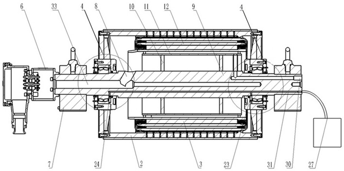
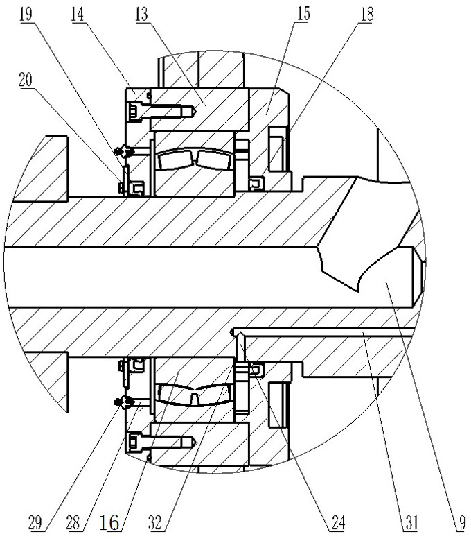
The invention relates to the field of transmission technology, and discloses a drum lubricating oil system, which mainly includes a main shaft (9), and positioning steps (32) are arranged at both ends of the main shaft (9), and the main shaft (9) An axial oil inlet passage (31) is provided at one end of the main shaft (9), and radial oil injection holes are respectively provided at both ends of the main shaft (9), and the oil inlet passage (31) communicates with the oil injection holes at both ends; the end cover assembly (4), the end cover assembly (4) is sleeved on both ends of the main shaft (9) through bearings. The invention satisfies the requirement of oiling the bearings at both ends at the same time, which improves the oiling speed; the overflow valve is adopted on the side of the end cover to realize the automatic overflow when the oil is full, avoiding maintenance of the bearings when stopping the machine, and improving the service life of the drum. While reducing costs, personal safety is guaranteed.

Description

technical field [0001] The invention relates to the technical field of transmission, and more specifically relates to a drum lubricating oil system. Background technique [0002] The permanent magnet drum has the advantages of simple structure, reliable operation, less loss, high efficiency, and direct drive control. It is especially suitable for low-speed, high-torque applications, so it is widely used in petroleum, mining, metallurgical and steel rolling industries. After working for a period of time, the outer rotor electric drum needs to fill the supporting bearing with lubricating oil to reduce friction and prolong the life of the bearing. [0003] The permanent magnet drum is an external rotor motor, which is always in working condition in the application of the conveyor belt conveyor. Lubricating oil needs to be added to the bearings about half a year. It needs to go deep underground to manually refuel, and inject lubricating oil from the oil injection hole on the sid...

Claims


Application Information

Patent Timeline
Patent Type & Authority Patents(China)
IPC IPC(8): F16C3/02F16C33/66F16C33/78F16C33/72F16N7/38
CPCF16C3/02F16C33/664F16C33/6659F16C33/723F16C33/7809F16C33/7823F16C2380/26F16N7/38F16N2210/14F16N2210/18
Inventor 张春晖陈俊强
Owner JIANGSU JIAXUAN INTELLIGENT IND TECH CO LTD
Learn More