
Collector core and flat solar collector adopting same

A heat-collecting plate core and plate core technology, which is applied in the field of solar thermal utilization, can solve the problems affecting the appearance of flat-plate solar collectors, low economic benefits and production efficiency, and a large amount of equipment and site investment, so as to improve solar energy. Light-to-heat conversion performance, equipment investment and time-consuming cancellation, high appearance effect

Active Publication Date: 2014-05-21
山东哲能赫太阳能有限公司
View PDF8 Cites 0 Cited by
  • Summary
  • Abstract
  • Description
  • Claims
  • Application Information

AI Technical Summary

Problems solved by technology

[0003] However, the heat-collecting plate cores used in traditional flat-panel solar collectors are all heat-absorbing film layers and tube-separated structures, and the material of the film layer is usually 0.15mm-0.2mm copper plate or 0.3mm-0.4mm aluminum plate, and the plate cross-section If the area is too small, the heat loss due to the lateral heat conduction of the film layer is relatively large. The film layer and the pipe arrangement are welded to combine the two into one. The effective welding width of the weld seam is 3-5mm. Limited, which inhibits the heat conduction of the heat from the light-to-heat conversion of the film layer to the circulating medium of the exhaust tube
[0004] During the welding process of the traditional collector plate core, due to the welding stress, the film layer will show scale-like undulations, which will be reflected in the appearance of the collector when exposed to light, and affect the appearance of the flat-plate solar collector.
[0005] In addition, the traditional welding process requires a large amount of equipment and site investment. The man-hours spent on welding the membrane layer and the row pipe account for 1 / 5 of the total production man-hours of the entire collector, and the economic benefits and production efficiency are low.

Method used


Image

  • Collector core and flat solar collector adopting same
  • Collector core and flat solar collector adopting same
  • Collector core and flat solar collector adopting same

Examples


Embodiment 1

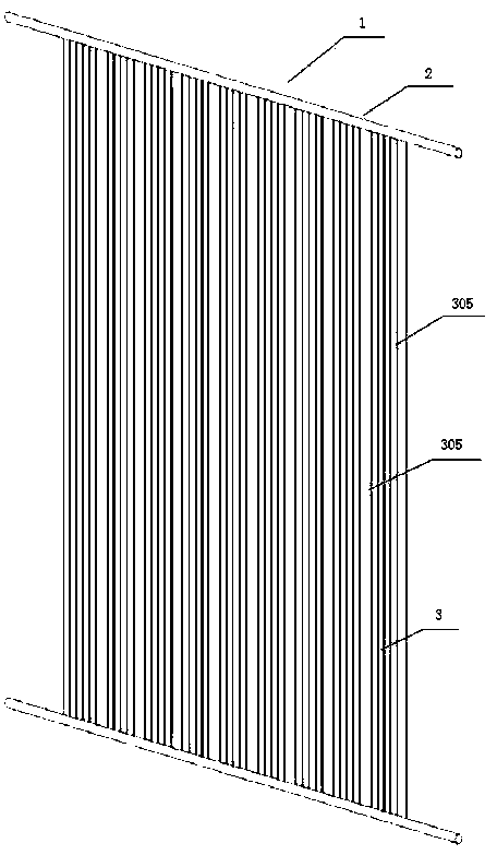
[0029] please combine Figure 1-2 , the heat collecting plate core 1 of the present invention includes plate core fins 3 and headers 2; The material 301 is connected by a connection design, the cavity between the two is a medium flow channel, 6 raised heat absorption strips 305 are arranged on the film substrate 301, and a fish card 304 is arranged on the exhaust pipe 302, which is reserved for the coating fixture. Slot; tube 302 is a closed U-shaped structure in cross section, and heat-conducting teeth 303 are arranged in tube 302. On the light-facing surface of film substrate 301, a highly selective absorption coating is made. A U-shaped flanging hole is punched and welded on the header 2 , and the plate-core fins 3 are connected to the header 2 through the arrangement of pipes 4 .

[0030] image 3 , 4 , 5 are the overlapping ways of the two core fins of the present invention.

[0031] like figure 1 , the heat collector plate core of the present invention is formed by ...

Embodiment 2

[0036] like Figure 7 As shown, the heat collecting plate core of the present invention is integrally drawn from an aluminum material, and there are no joints between the plate core fins.


PUM


Abstract

The invention relates to a collector core, which is used on a flat solar collector. The collector core comprises core fins and headers, the surface of each core fin is a film substrate, a plurality of raised heat-absorbing strips are arranged on the surface of the film substrate, a tube is arranged on one end of the film substrate, flanged welding holes are punched on the headers, and the core fins are connected with the headers through the tubes. The flat solar collector adopting the collector core comprises the collector core, a frame, a bottom plate and a glass cover board, the collector core is packaged in the cavity defined by the frame, the bottom plate and the glass cover board, an air interlayer is arranged between the collector core and the glass cover board, heat-insulating material is filled between the collector core and the bottom plate, and sealing materials are adopted for sealing between the frame and the glass cover board and between the frame and the bottom plate. The heat-collecting performance of the collector core is excellent, the appearance of the collector core is attractive, and the production efficiency of the collector core is excellent.

Description

technical field [0001] The invention relates to the technical field of solar light and heat utilization, in particular to a novel heat collecting plate core used for a flat-plate solar heat collector, and a flat-plate solar heat collector using the heat collecting plate core. Background technique [0002] Due to the advantages of low cost, stable performance, long life, good safety, and easy realization of integrated solar energy and building design, flat-plate solar collectors have gradually been recognized by the market. [0003] However, the heat-collecting plate cores used in traditional flat-panel solar collectors are all heat-absorbing film layers and tube-separated structures, and the material of the film layer is usually 0.15mm-0.2mm copper plate or 0.3mm-0.4mm aluminum plate, and the plate cross-section If the area is too small, the heat loss due to the lateral heat conduction of the film layer is relatively large. The film layer and the pipe arrangement are welded ...

Claims


Application Information

Patent Timeline
Patent Type & Authority Patents(China)
IPC IPC(8): F24J2/46F24J2/48
CPCY02E10/40
Inventor 周雄峰周淑军
Owner 山东哲能赫太阳能有限公司
Learn More