Eureka AIR delivers breakthrough ideas for toughest innovation challenges, trusted by R&D personnel around the world.

Minimum transmission differential signal receiver system and built-in self testing method thereof

A technology of differential signal and test method, applied in transmission systems, transmission monitoring, electrical components, etc., can solve the problems of multiple test circuits, cost of chip area, etc.

Inactive Publication Date: 2012-09-05
NOVATEK MICROELECTRONICS CORP
View PDF4 Cites 2 Cited by
  • Summary
  • Abstract
  • Description
  • Claims
  • Application Information

AI Technical Summary

Problems solved by technology

Furthermore, a general TMDS receiver system usually has three data channels, requiring more test circuits, which will also result in cost of chip area.

Method used


Image

  • Minimum transmission differential signal receiver system and built-in self testing method thereof
  • Minimum transmission differential signal receiver system and built-in self testing method thereof
  • Minimum transmission differential signal receiver system and built-in self testing method thereof

Examples


Embodiment Construction

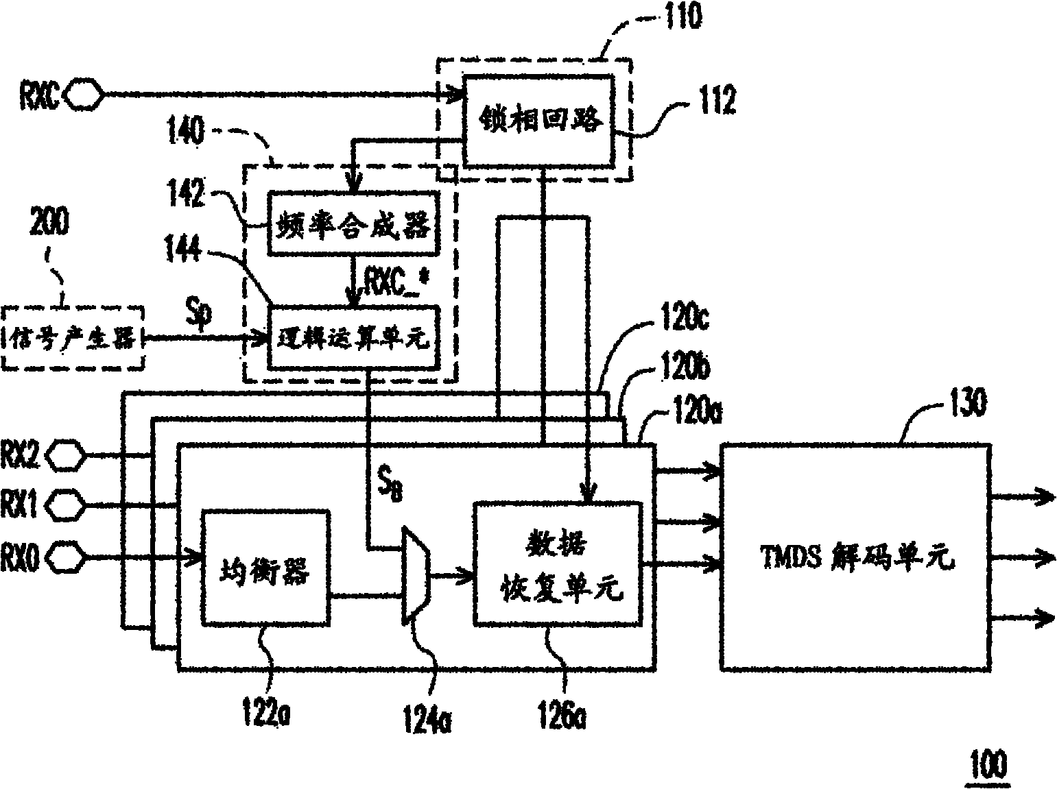
[0039] figure 1 A functional block diagram of a TMDS receiver system according to an embodiment of the present invention is shown. Please refer to figure 1 , the TMDS receiver system 100 of this embodiment includes a clock channel 110 , multiple data channels 120 a , 120 b , 120 c , a TMDS decoding unit 130 and a self-test unit 140 .

[0040] In this embodiment, the clock channel 110 includes a phase-locked loop 112 . The PLL 112 receives a clock signal RXC, and outputs the clock signal RXC to the self-test unit 140 and the data channels 120a, 120b, 120c after synchronization.

[0041] The data channels 120a, 120b, 120c receive, process and output corresponding data signals RX0, RX1, RX2 according to the clock signal RXC. Here, the data channels 120a, 120b, 120c are, for example, recovering and repairing the received data signals RX0, RX1, RX2. Therefore, the data channels 120a, 120b, and 120c of this embodiment respectively include an equalizer, a selector, and a data res...


PUM


Abstract

The invention discloses a minimum transmission differential signal receiver system and a built-in self testing method thereof. The system comprises a clock channel, multiple data channels, a minimum transmission differential signal decoding unit and a self testing unit, wherein the clock channel receives and outputs a clock signal, each data channel receives, processes and outputs a corresponding data signal according to the clock signal; the minimum transmission differential signal decoding unit receives the data signal after processing, and can decode the data signal after the processing; and the self testing unit receives the clock signal and an external parallel signal, generates a test signal according to the clock signal and the external parallel signal, and can perform built-in self testing on the data channels and the minimum transmission differential signal decoding unit. In addition, the built-in self testing method which is suitable for the minimum transmission differential signal receiver system is provided.

Description

technical field [0001] The present invention relates to a receiver system and a testing method thereof, and in particular to a Transition Minimized Differential Signaling (TMDS) receiver system and a built-in self-test (Built-in-self-test, BIST) )method. Background technique [0002] TMDS is a high-speed data transmission technology that can be used for image transmission interfaces such as Digital Visual Interface (DVI) and High-Definition Multimedia Interface (HDMI). Generally speaking, a TMDS receiver system has four channels, three of which are data channels, which respectively receive image signals in YUV format or RGB format, and the other is a clock channel, which is used to receive clock signals, and the maximum of each channel The transmission speed is 1.65Gbps. [0003] In a TMDS receiver system, a typical built-in self-test method usually replaces the original data channel, and uses the built-in test circuit to generate signals to achieve the purpose of self-tes...

Claims


Application Information

Patent Timeline
IPC IPC(8): H04B1/06H04B17/00H04B17/19
Inventor 林佳欣
Owner NOVATEK MICROELECTRONICS CORP
Why Eureka
Eureka Blog
Learn More