Broadband linear equalization circuit

A technology of linear equalization and equalization circuit, applied in the direction of logic circuit connection/interface layout, logic circuit coupling/interface using field effect transistors, etc. problems such as complexity and power consumption, to achieve the effect of large high-frequency gain, power consumption advantage, and area advantage

Inactive Publication Date: 2013-10-09
PEKING UNIV +1
View PDF6 Cites 22 Cited by
  • Summary
  • Abstract
  • Description
  • Claims
  • Application Information

AI Technical Summary

Problems solved by technology

However, increasing the capacitor value to increase the high-frequency gain of the equalizer will reduce the dominant pole of the resistor-capacitor negative feedback equalization circuit and sacrifice bandwidth. A compromise between this bandwidth and high-frequency gain makes it Difficulty coping with increasing data rate bandwidth and gain requirements
[0006] At present, many studies have made improvements to this problem. For example, Gondi, S. and Razavi, B. et al. use passive inductance to extend the bandwidth, but the on-chip passive inductance will bring a large area cost (reference: Gondi S, and Razavi B. "Equalization and clock and data recovery techniques for 10G / s CMOS serial-link receiver," IEEE J.of Solid-State Circuits, 2007, vol.42, no.9, pp.1999-2011), Although the active inductor used by E. Sackinger et al. reduces the chip area, it requires a high voltage generated by the charge pump higher than the power supply voltage, which increases the complexity and power consumption of the circuit (references: Sackinger E, and Fischer W C.A3GHz32-dB CMOS limiting amplifier for SONET OC-48receivers.IEEE J.of Solid-State Circuits,2000,vol.35,no.12,pp.1884-1888)

Method used


Image

  • Broadband linear equalization circuit
  • Broadband linear equalization circuit
  • Broadband linear equalization circuit

Examples


Embodiment Construction

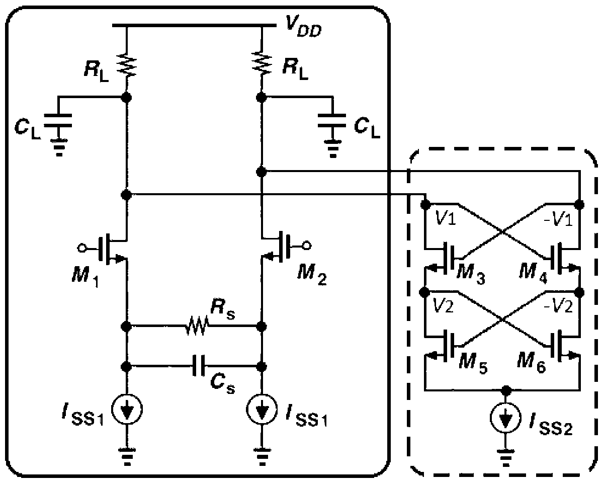
[0025] The novel broadband linear equalization circuit of the present invention is as figure 1 As shown, it includes a traditional resistor-capacitor negative feedback equalization circuit, such as figure 1 Shown in the solid line box, and an active inductor structure composed of four NMOSs M3, M4, M5, and M6. The drain of M3 in the active inductance is connected to a differential output terminal of the negative feedback circuit of the original capacitor resistor, that is, the drain terminal of M1; the drain of M4 is connected to the other differential output terminal of the negative feedback circuit of the original capacitor resistor, that is, the output terminal of M2 leaky end.

[0026] The transfer equation of the traditional resistor-capacitor negative feedback equalization circuit is:

[0027] H ( S ) = g m 1 ...


PUM


Abstract

The invention discloses a broadband linear equalization circuit which comprises a capacitor resistor negative feedback equalization circuit. The broadband linear equalization circuit is characterized by further comprising a difference active inductor structure. The two input ends of the difference active inductor structure are connected with the two difference output ends of the capacitor resistor negative feedback equalization circuit respectively. The difference active inductor structure provides a null point and a pair of conjugate complex number poles, wherein high-frequency gain peak values can be introduced by the conjugate complex number poles, and the null point can eliminate a main pole point of the capacitor resistor negative feedback equalization circuit. Compared with the prior art, the broadband linear equalization circuit can provide wider band width and larger high-frequency gains, and has advantages on the area and power consumption.

Description

technical field [0001] The invention relates to an equalizing circuit, in particular to a broadband linear equalizing circuit, which belongs to the technical field of communication. Background technique [0002] Compared with parallel connection, high-speed serial interface technology has the advantages of low cost and good anti-interference performance. It is the mainstream technology for high-speed interface and large data transmission. It is widely used in the fields of network communication, backplane connection and input and output interfaces. . With the growth of application requirements and the advancement of related technologies, the data rate of high-speed serial transmission is getting faster and faster, which puts forward higher and higher requirements for the bandwidth of the transceiver circuit. [0003] The transmission and reception of high-speed serial data must pass through the signal transmission medium, that is, the channel. A complete channel generally ...

Claims


Application Information

Patent Timeline
Patent Type & Authority Applications(China)
IPC IPC(8): H03K19/0185
Inventor 李路盖伟新
Owner PEKING UNIV
Why Eureka
Try Eureka