
Motor vehicle air-conditioning loop comprising a volume expansion chamber

An air-conditioning circuit, volume expansion technology, applied in vehicle components, refrigerators, mechanical equipment, etc., can solve problems such as detrimental to the comfort of passengers

Inactive Publication Date: 2012-09-05
RENAULT SA
View PDF7 Cites 0 Cited by
  • Summary
  • Abstract
  • Description
  • Claims
  • Application Information

AI Technical Summary

Problems solved by technology

[0007] However, in operation, the compressor 1 generates pulsating pressure waves that are transmitted towards the condenser 4 and towards the evaporator 5, thereby causing noise that can be detrimental to the comfort of the occupants

Method used


Image

  • Motor vehicle air-conditioning loop comprising a volume expansion chamber
  • Motor vehicle air-conditioning loop comprising a volume expansion chamber
  • Motor vehicle air-conditioning loop comprising a volume expansion chamber

Examples


Embodiment Construction

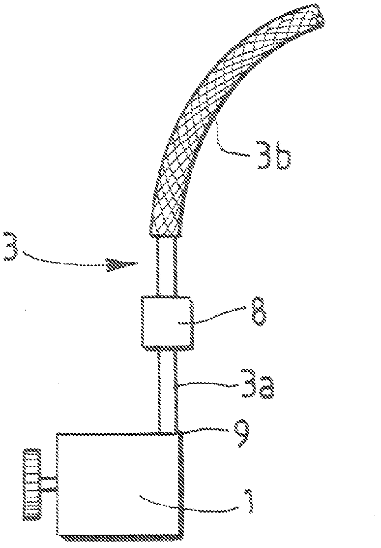
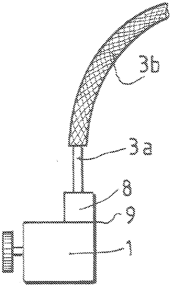
[0030] image 3 The innovation provided by the invention, namely the direct connection of the volume expansion chamber 8 to the inlet 9 of the compressor 1 is schematically shown.

[0031] In this case, connected to the evaporator 5 by a rigid pipe 3a as well as a flexible pipe 3b is a low pressure inlet.

[0032] Such as Figure 4 As shown in , the volume expansion chamber 8 is fixed to the casing of the compressor 1 in a rigid manner, and as Figure 5 integrated in the rigid tube 3a ( Figure 5 Not shown in) on the fixing flange 10.

[0033] This flange 10 has a first opening 11 intended to be connected to the rigid tube 3a and a second opening 12 positioned at 90° to the first opening 11 and intended to be connected to a compression On the entrance 9 of machine 8.

[0034] This second opening 12 leads to a connector 13 having a hole, for example 14 , for the passage of a screw so that this connector 13 can be fastened to the inlet 9 of the compressor 1 .

[0035] Refr...


PUM


Abstract

The invention relates to a motor vehicle air-conditioning loop comprising a compressor (1) connected to a condenser and to an evaporator by means of pipes, each of which includes a rigid pipe (3a) connected to a flexible pipe (3b), as well as a volume expansion chamber (8) which dampens the pulsed pressure waves generated by the compressor (1) and is arranged between the compressor (1) and one of the flexible pipes (3b), characterized in that said volume expansion chamber (8) is connected directly to the inlet (9) or to the outlet of the compressor (1).

Description

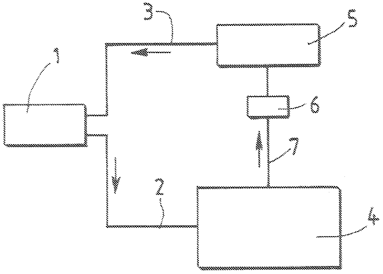
technical field [0001] The invention relates to a motor vehicle air conditioning circuit. Background technique [0002] Such as figure 1 As shown, the air conditioning circuit of a motor vehicle comprises a compressor 1 connected by ducts 2, 3 to a condenser 4 and to an evaporator 5 which distributes cooled air into the passenger compartment of the vehicle. [0003] An expander 6 is provided on the line 7 connecting the condenser 4 with the evaporator 5 . [0004] The compressor 1 is driven by the engine of the vehicle. [0005] Conduits 2 and 3 each have a rigid tube, such as 3a, connected to a flexible tube, such as 3b (see figure 2 ). [0006] These flexible pipes such as 3b are necessary to avoid movement of the compressor 1 since the vibrations of the engine are transmitted to the condenser 4 and evaporator 5 . [0007] However, in operation, the compressor 1 generates pulsating pressure waves which are transmitted towards the condenser 4 and towards the evaporato...

Claims


Application Information

Patent Timeline
Patent Type & Authority Applications(China)
IPC IPC(8): B60H1/00F16L55/02
CPCB60H1/00571B60H2001/006F25B2500/12
Inventor A·埃尔南德斯-加西亚I·圣地亚哥-卡斯特莱诺
Owner RENAULT SA
Learn More