Alignment light path device applied to retinal imaging system

An imaging system and light alignment technology, which is applied in the field of biometrics and medical optical instruments, can solve problems such as the inability to guarantee the working distance and the decrease in the edge definition of retinal images, and achieve the effect of high adjustment accuracy and clear adjustment goals in terms of operation

Inactive Publication Date: 2012-09-12
CHANGCHUN CHANGGUANG SIPO SPECTRUM TECH
View PDF11 Cites 7 Cited by
  • Summary
  • Abstract
  • Description
  • Claims
  • Application Information

AI Technical Summary

Problems solved by technology

[0007] In order to solve the problem that the working distance cannot be guaranteed to be the design value in the existing retinal imaging system and the

Method used


Image

  • Alignment light path device applied to retinal imaging system
  • Alignment light path device applied to retinal imaging system
  • Alignment light path device applied to retinal imaging system

Examples


Embodiment Construction

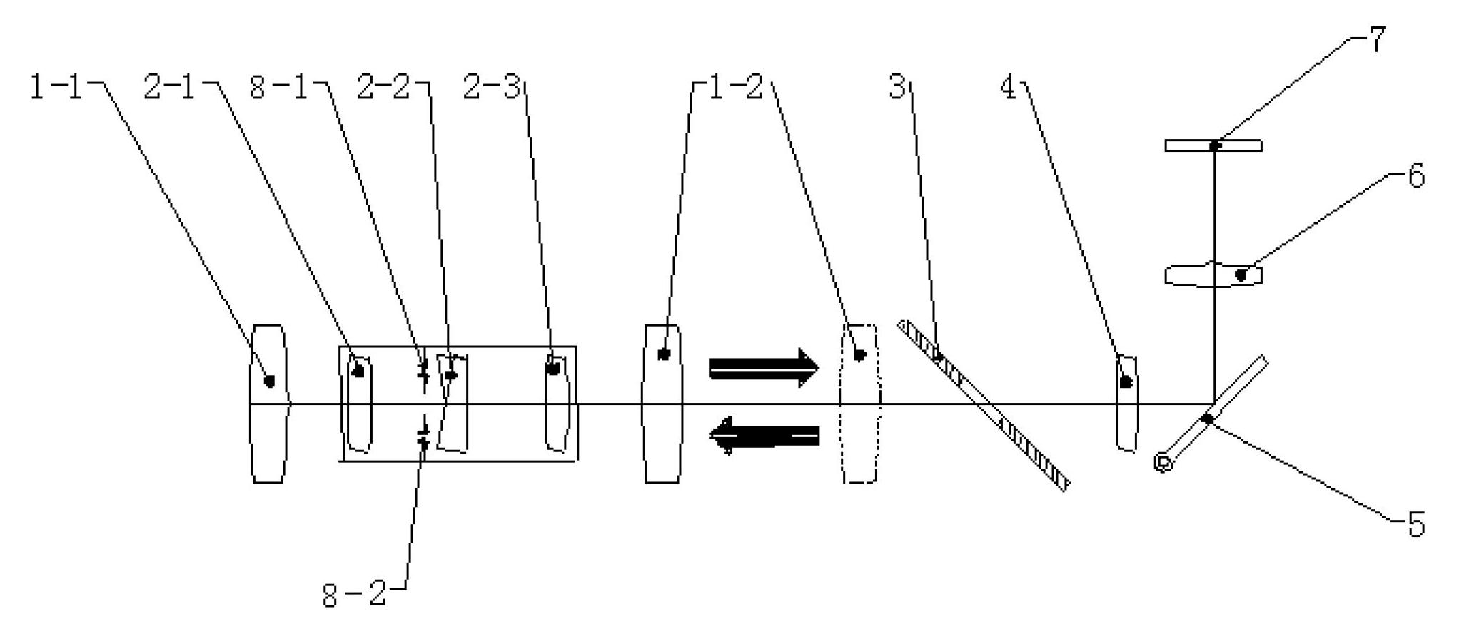
[0014] Such as figure 1 As shown, the alignment optical path device applied to the retinal imager includes a retinal objective lens fixed group 1-1, a retinal objective lens zoom group 1-2, a switching mirror group 2, a hollow mirror 3, a first relay mirror 4, a second A reflector 5, a second relay mirror 6 and a near-infrared light detector 7. Retinal objective fixed group 1-1, retinal objective zoom group 1-2, switching mirror group 2, hollow mirror 3, first relay mirror 4 and first reflector 5 are coaxially placed. A switching lens group 2 is arranged between the retinal objective lens fixed group 1-1 and the retinal objective lens zoom group 1-2. The light sent by the iris passes through the retina objective lens fixed group 1-1, the switching lens group 2, the retina objective lens zoom group 1-2, the hollow reflector 3, the first relay mirror 4 and the first reflector 5, and the light passes through the first A reflector 5 is incident to the second relay mirror 6 after...


PUM


Abstract

The invention discloses an alignment light path device applied to a retinal imaging system and belongs to the field of medical optical instruments and biometric identification. The invention aims to solve the problem that the marginal definition of retinal pictures is reduced because the working distance cannot be ensured to be a design value in the prior art. The device comprises a retinal objective fixation group, a retinal objective zooming group, a switching lens group, a hollow reflective mirror, a first relay lens, a first reflective board, a second relay lens and a near infrared photodetector, wherein the switching lens group is arranged between the retinal objective fixation group and the retinal objective zooming group, and an optical signal sent by an iris sequentially passes through the retinal objective fixation group, the retinal objective zooming group, the switching lens group, the hollow reflective mirror, the first relay lens, the first reflective board and the second relay lens, and is received by the near infrared photodetector; the switching lens group comprises a switching lens front group, a double optical wedge and a switching lens rear group; and the double optical wedge is a combination of two optical wedges which are arranged in parallel and have opposite inclined directions. An alignment method is high in adjusting accuracy, and can be widely applied to retinal imaging systems.

Description

technical field [0001] The invention relates to an alignment optical path device applied to a retinal imaging system, and belongs to the fields of medical optical instruments and biometric identification. Background technique [0002] Retinal imaging technology is gradually being widely used in fields such as medical treatment and biometric identification. In medicine, timely detection and tracking of retinopathy can play an effective role in diagnosis and early warning of various diseases. In the field of biometrics, the retina has far more biological characteristics than fingerprints and palmprints, which can greatly improve the recognition accuracy; moreover, the retina penetrates into the fundus of the eye and is not easy to be obtained by the outside world, so it has a very high level of confidentiality. [0003] The retinal imager consists of three necessary components: imaging light path, illumination light path and positioning light path. The imaging light path and ...

Claims


Application Information

Patent Timeline
IPC IPC(8): A61B3/15
Inventor 李淳刘英孙强李灿
Owner CHANGCHUN CHANGGUANG SIPO SPECTRUM TECH
Why Eureka
Try Eureka