Guide rail and sliding block transmission mechanism for forging

A technology of guide rail slider and transmission mechanism, which is applied in the field of guide rail slider transmission mechanism and forging guide rail slider transmission mechanism, which can solve the problems of low production efficiency, large energy consumption, and low forging efficiency, and achieve high production efficiency and low energy consumption. less, high forging efficiency

Inactive Publication Date: 2012-09-12
姜秀新
View PDF0 Cites 5 Cited by
  • Summary
  • Abstract
  • Description
  • Claims
  • Application Information

AI Technical Summary

Problems solved by technology

[0005] Beneficial effects: Since the present invention adopts the magnetic force of high-energy magnets as the power transmission mode, the whole mechanism has the advantages of high forging efficiency, less energy consumption, and high production efficiency, thereby achieving the purpose of the present invention and effectively overcoming the problems of existing forging presses. The defects of low forging efficiency, large energy consumption and low production efficiency in the guide rail slider transmission mechanism

Method used


Image

  • Guide rail and sliding block transmission mechanism for forging
  • Guide rail and sliding block transmission mechanism for forging

Examples


Embodiment Construction

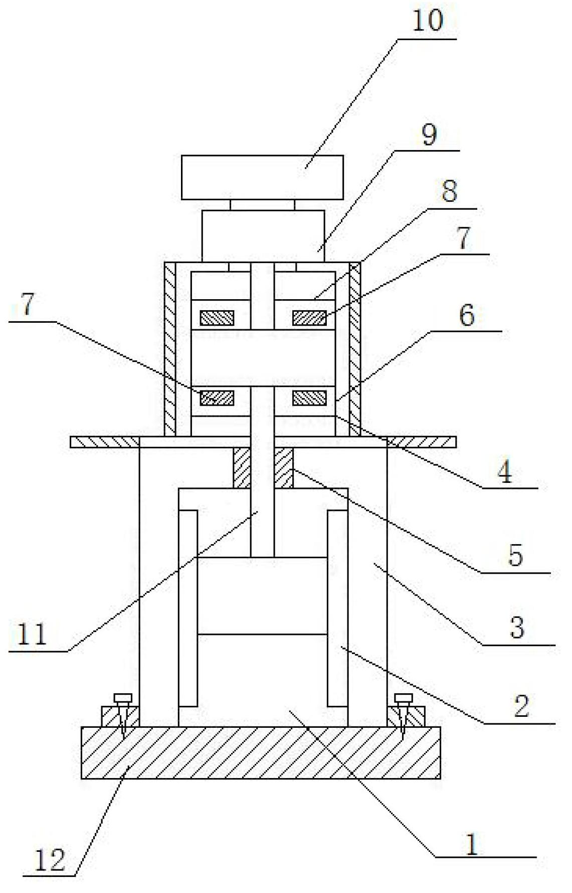
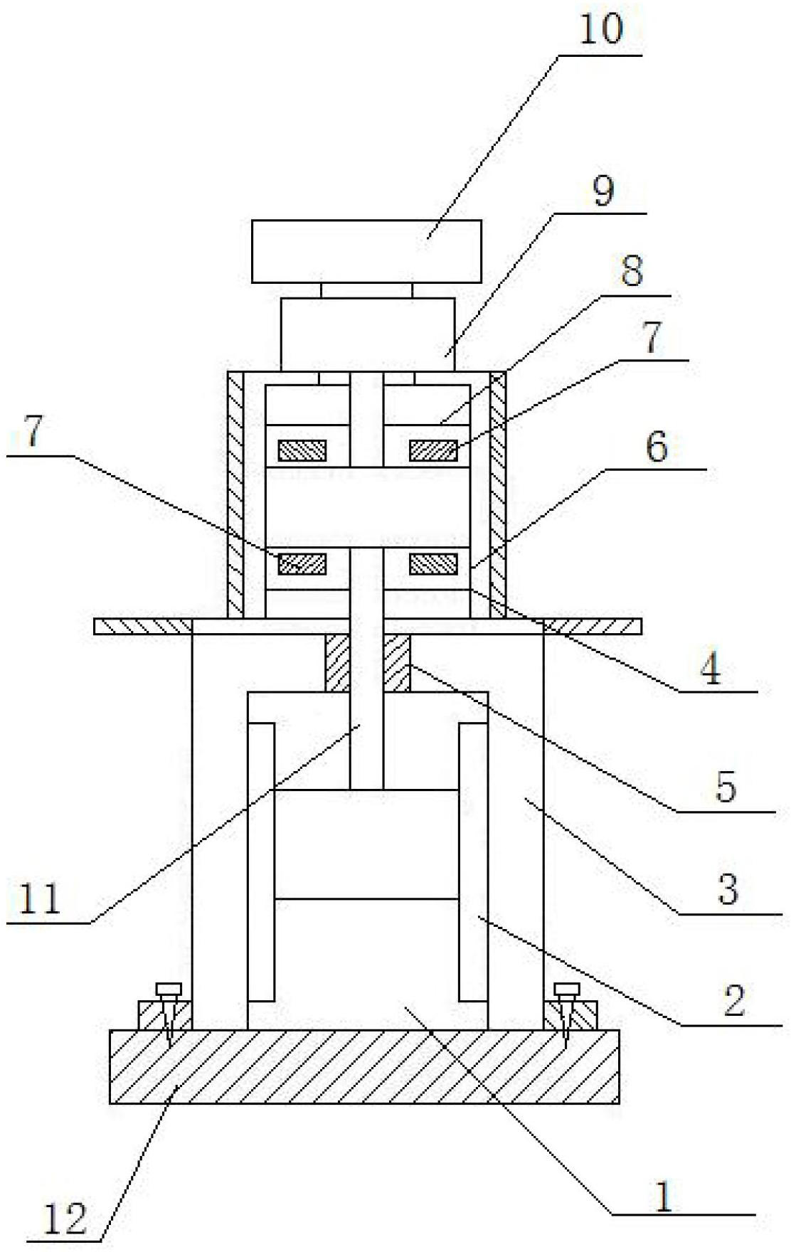
[0009] The guide rail slider transmission mechanism has a slider (1), the slider (1) is installed on the mechanism body (3) through the double-action guide rail (2), and a sliding bearing (5) is installed on the top of the mechanism body (3). The drive shaft (11) passes through the slider bearing (5) and connects with the slider (1) through the bottom of the transmission drive shaft (11), and the transmission drive disc (6) is installed on the transmission drive shaft (11) ), a high-energy magnet (7) is connected to the transmission drive plate (6), the polarity of the high-energy magnet (7) is opposite, and it is symmetrically embedded in the transmission drive plate (6); on the top of the mechanism body (3) is installed a square Bracket (4), the centerline of the square bracket (4) is concentric with the centerline of the transmission drive disk (6), and the transmission drive disk (6) is connected with a dual-frequency rotating disk (8), a dual-frequency rotating disk (8) I...


PUM


Abstract

A guide rail and sliding block transmission mechanism for forging is mounted on a mechanism body through a sliding block and a double acting guide rail. A sliding block bearing is mounted on the top of the mechanism body. A transmission driving shaft penetrates through the sliding block bearing and is connected with the sliding block through the bottom of the transmission driving shaft. A transmission driving disc is mounted above the transmission driving shaft. High energy magnets with opposite polarities are connected to the transmission driving disc and embedded in the transmission driving disc symmetrically. A square support is mounted on the top of the mechanism body and the central line of the square support is concentric with that of the transmission driving disc. A double-frequency rotating disc is connected to the transmission driving disc. The double-frequency rotating disc is mounted on an output shaft of a reducer. High energy magnets with opposite polarities are embedded in the double-frequency rotating disc symmetrically. The reducer is mounted on the upper portion of the square support. A multi-frequency motor is mounted on the reducer and an output shaft of the multi-frequency motor is connected with the reducer.

Description

technical field [0001] The invention relates to a transmission mechanism of a slide block of a guide rail, in particular to a transmission mechanism of a slide block of a forging guide rail, which belongs to the technical field of forging equipment. Background technique [0002] The mechanical guide rail slider transmission mechanism of forging press equipment is an important component of the forging press machine. At present, the forging press machine adopts the transmission mode of the crank connection mechanism in the transmission mode. This transmission mode has complex structure, low forging efficiency, and large energy consumption. , The defect of low production efficiency. Contents of the invention [0003] The purpose of the present invention is to provide a forging guide rail slider transmission mechanism with high forging efficiency, low energy consumption and high production efficiency, so as to overcome the above-mentioned defects in the existing forging press ...

Claims


Application Information

Patent Timeline
Patent Type & Authority Applications(China)
IPC IPC(8): B21J9/18
Inventor 姜秀新
Owner 姜秀新
Why Eureka
Try Eureka