Self-charging sensor faucet device

A faucet and self-charging technology, applied in the direction of circuit devices, battery circuit devices, valve devices, etc., can solve the problems of battery replacement, inconvenient use, frequent replacement of batteries, affecting reliability, etc., and achieve wide application prospects and promotion value. Effects of low cost and improved reliability

Active Publication Date: 2012-09-12
海宁经开产业园区开发建设有限公司
View PDF7 Cites 4 Cited by
  • Summary
  • Abstract
  • Description
  • Claims
  • Application Information

AI Technical Summary

Problems solved by technology

In order to overcome the above problems, the Chinese Utility Model Patent No. 200620104532.0 discloses an "integrated sensor smart faucet", which includes a faucet body, a sensor device, a lithium battery, and a sensor solenoid valve. The technology can effectively improve the faucet switch in "outdoor" and public places, avoiding the waste of water resources. It has the advantages of reasonable design, convenient installation and maintenance, etc. The disadvantage is that the battery needs to be replaced frequently, which makes it inconvenient to use.
In order to overcome the trouble of frequently replacing dry batteries, the Chinese patent No. 200920104006.8 discloses an "automatic charging induction faucet". Control module, the impeller with rotating shaft is installed in the water inlet pipe between the solenoid valve and the faucet body. Solve the problem that the battery of the existing induction faucet needs to be replaced frequently and is inconvenient to use, but because one end of the shaft of the impeller is connected to a generator, that is, the impeller and the generator use the same shaft, although the shaft is sealed by a rubber sealing ring. Transmission, but after a certain period of use, wear and water leakage often occur, which causes the contact of the generator winding with water, seriously affecting the reliability of long-term use

Method used


Image

  • Self-charging sensor faucet device
  • Self-charging sensor faucet device
  • Self-charging sensor faucet device

Examples


Embodiment Construction

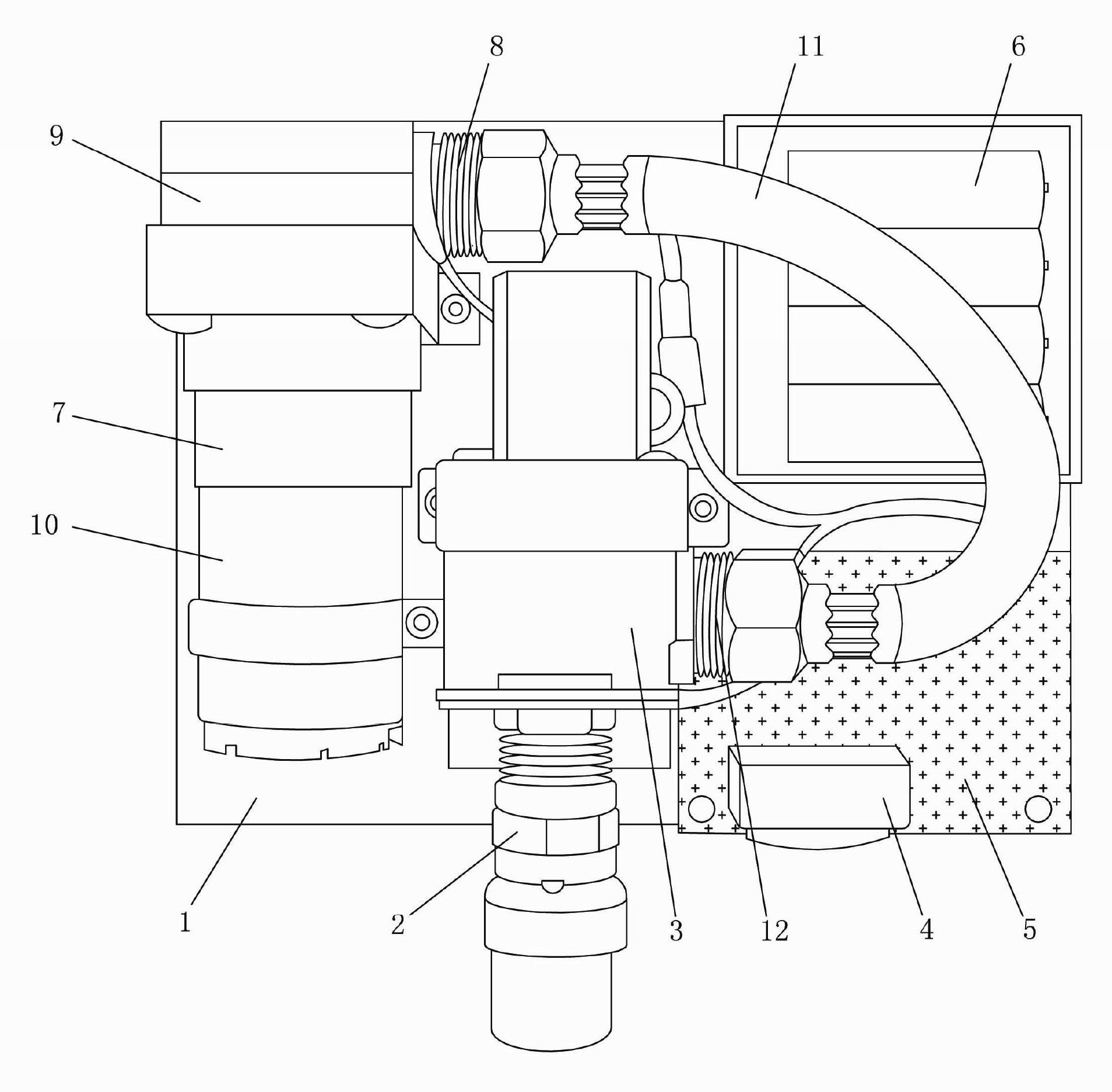
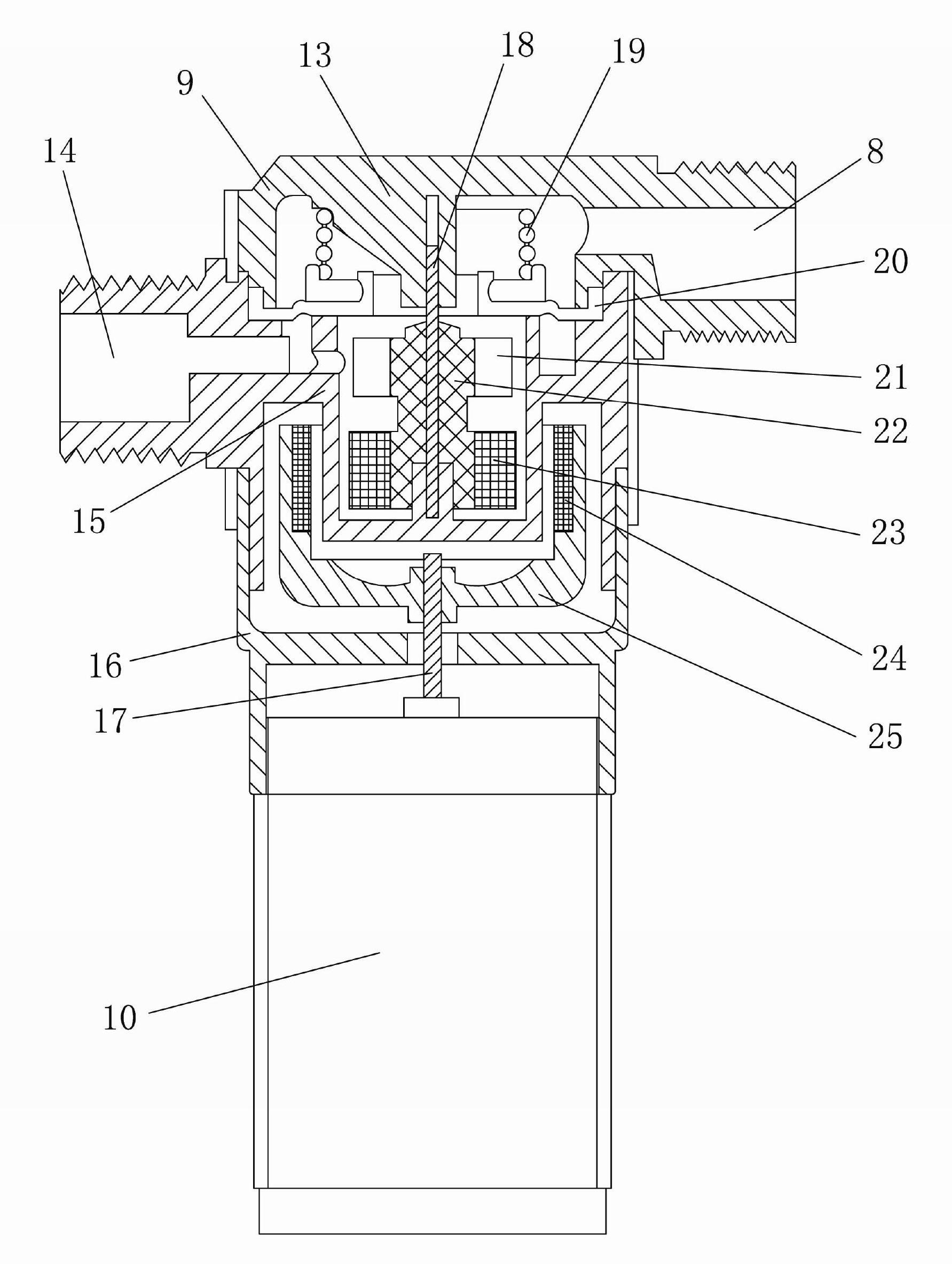
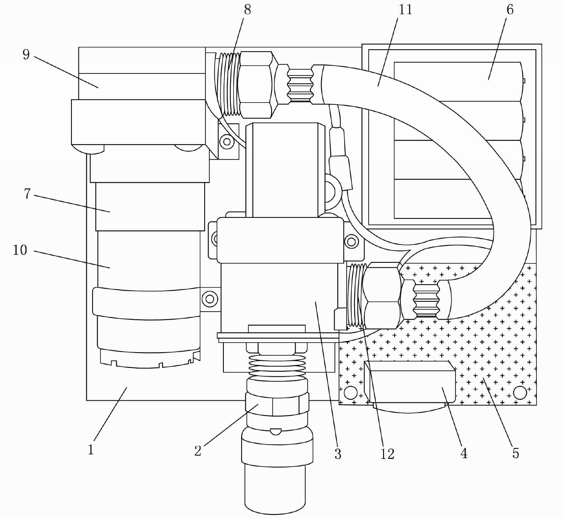
[0011] The present invention will be described in further detail below in conjunction with the accompanying drawings. Referring to the accompanying drawings, this self-charging induction faucet device of the present invention includes a housing, a positioning board 1, a circuit control board 5, an electronic induction head 4 with an induction window, a faucet body 2 with a solenoid valve, and a power supply device. It is characterized in that: the main body 2 of the faucet with a solenoid valve is installed in the middle of the positioning plate 1, the circuit control board 5 is installed in the lower right side of the positioning plate 1, and the electronic induction head 4 is installed near the outlet of the main body of the faucet. The right side of the nozzle (located at the lower left part of the circuit control board), the above-mentioned design can realize reasonable and compact installation, and the solenoid valve 3 is controlled by the positive and negative pulses outp...


PUM


Abstract

The invention discloses a self-charging sensor faucet device which is characterized in that a faucet main body with an electromagnetic valve is arranged in the middle of a locating plate, a circuit control plate is arranged below the right side of the locating plate, an electronic induction head is arranged at the right side surface close to a water outlet of the faucet main body, the electromagnetic valve is controlled by positive and negative pulses output by the electronic induction head; a power supply device comprises a pipe flow type water-wheel generator arranged at the left side of the locating plate, rechargeable batteries and a charger; the water-wheel generator comprises a water turbine body part consisting of an impeller cavity and a cavity cover body which are connected in a sealing manner, the impeller cavity and a generator body are connected by a flange sealing ring in a sealing manner, a multi-pole magnetic ring is arranged on an impeller rotating shaft, a magnetic ring sleeve with a multi-pole magnetic loop is arranged on a generator rotating shaft, and the assembled multi-pole magnetic loop is arranged corresponding to the multi-pole magnetic ring and is in coupling connection transmission with the multi-pole magnetic ring. According to the self-charging sensor faucet device, the service life of a power supply can be greatly prolonged, the water turbine part and the generator part can be completely and independently installed, the contact between the generator and water is eliminated, and the long-term use reliability is improved.

Description

technical field [0001] The invention relates to an induction faucet, in particular to a self-charging induction faucet device which utilizes the impulse force of water flow in a water pipe to generate electricity. Background technique [0002] In daily life, we often find that the faucets on the side of the road are dripping. Some people who exercise in the park forgot to turn it off or did not close it tightly after using it. The class bell rang after the classmate used it, and hurried back to class without turning off the faucet, so that the water was wasted in vain. Statistics show that after using the faucet, 75.8% of the people sometimes don’t turn it off and don’t know whether they have turned it off or not, while only 24.2% of the people can turn it off. The vast majority of people use the faucet outdoors. Sometimes the proportion of people who don't turn it off and don't know whether they have turned it off or not is very large. Therefore, from this statistics, we c...

Claims


Application Information

Patent Timeline
Patent Type & Authority Applications(China)
IPC IPC(8): F16K31/06F03B13/00H02J7/00
Inventor 苏宁远吕少永
Owner 海宁经开产业园区开发建设有限公司
Why Eureka
Try Eureka