Light driving scanning micro-mirror

A scanning micromirror and light-driven technology, applied in optics, optical components, microstructure technology, etc., can solve the problems of metal wire bonding process failure, avoid metal wire bonding process, reduce device size, and improve reliability. and safety effects

Inactive Publication Date: 2015-04-01
蚌埠尚维知识产权运营有限公司
View PDF7 Cites 0 Cited by
  • Summary
  • Abstract
  • Description
  • Claims
  • Application Information

AI Technical Summary

Problems solved by technology

There is a certain risk of failure in the metal wire bonding process

Method used


Image

  • Light driving scanning micro-mirror
  • Light driving scanning micro-mirror

Examples


Embodiment Construction

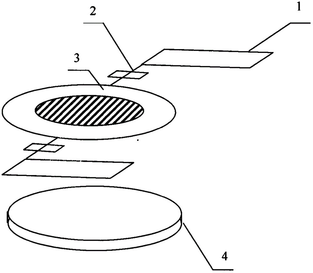
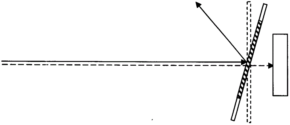
[0017] Below in conjunction with accompanying drawing and embodiment the present invention will be further described: as Figure 1-2 As shown, it includes a micro-driver 1, a planar spring 2, a movable mirror 3 and a photocell 4. The output end of the micro-driver 1 is connected with the input end of the planar spring 2, the output end of the planar spring 2 is connected with the input end of the movable mirror 3, and the output end of the photocell 4 is connected with the input end of the micro-driver 1; each device includes 1 A movable mirror 3, two planar springs 2, two micro-drivers 1 and a photocell 4, the movable mirror 3 is connected with two planar springs 2, and each planar spring 2 is connected with a micro-driver 1;

[0018] The micro-driver 1 is made using micro-machining technology, based on the principle of electrothermal drive, and is composed of multi-layer materials such as silicon, silicon dioxide, metal, metal oxide, etc., and is used to pass the externally ...


PUM


Abstract

The invention provides a light driving scanning micro-mirror, comprising micro-drivers, plane springs, a movable lens and a light cell. Output ends of the micro-drivers are connected with input ends of the plane springs; output ends of the plane springs are connected with an input end of the movable lens; and an output end of the light cell is connected with input ends of the micro-drivers. Each light driving scanning micro-mirror comprises one movable lens, two plane springs, two micro-drives and one light cell; and the movable lens is connected with the two plane springs; each plane spring is connected with one micro-driver. The light driving scanning micro-mirror provided by the invention is manufactured by using a silicone micromachining technology, and the lens can be directly driven through a specific wave length in incidence laser to scan, so that a lead wire bonding process related to the traditional electric connection is avoided.

Description

technical field [0001] The invention relates to a microelectromechanical system device for optical scanning, in particular to the light driving principle based on photoelectric conversion technology. Background technique [0002] Micro optical scanning devices manufactured by silicon micromachining technology have very important applications in optical scanning, optical imaging, laser projection and other fields. Especially in the field of optical endoscopic imaging, imaging probes integrated with micro-optical scanning devices can scan in various diameters of the human body (such as blood vessels, digestive tracts, etc.), and combine with external optical imaging equipment to obtain Two-dimensional images or three-dimensional images of human tissue. [0003] Usually, micro optical scanning devices use aluminum or gold wire bonding technology to establish a stable and reliable electrical connection between the pad on the surface of the device and the external metal wire, so...

Claims


Application Information

Patent Timeline
Patent Type & Authority Patents(China)
IPC IPC(8): G02B26/10B81B7/00
Inventor 徐英舜
Owner 蚌埠尚维知识产权运营有限公司
Why Eureka
Try Eureka