
Method for acquiring road information based on laser ranging node system

A technology of laser ranging and road information, which is used in distance measurement, traffic control system, traffic control system of road vehicles, etc., can solve the problems of low vehicle type recognition rate, inability to discriminate vehicles carefully, and low vehicle sampling rate, etc. Good application effect, simple application, good application scalability

Active Publication Date: 2012-09-12
THE THIRD RES INST OF MIN OF PUBLIC SECURITY
View PDF7 Cites 22 Cited by
  • Summary
  • Abstract
  • Description
  • Claims
  • Application Information

AI Technical Summary

Problems solved by technology

However, this type of information collection has many disadvantages, such as the need to use two sets of light sensor systems; the need to set reflective tape on the road; if the desired effect of this patent is to be achieved, the sensor needs to scan back and forth at a speed of hundreds or even Thousands of hertz, the mechanical scanning structure of such a scanning range is difficult to achieve
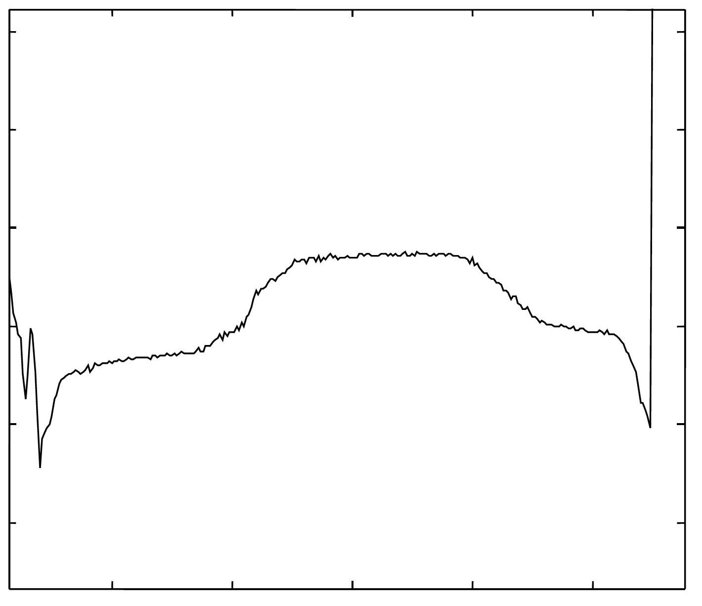
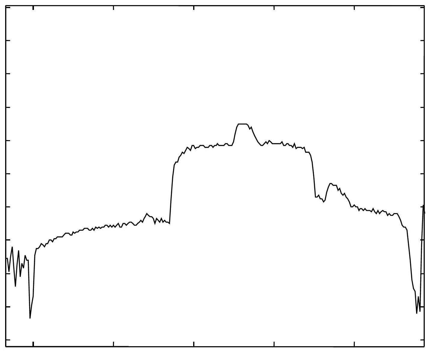
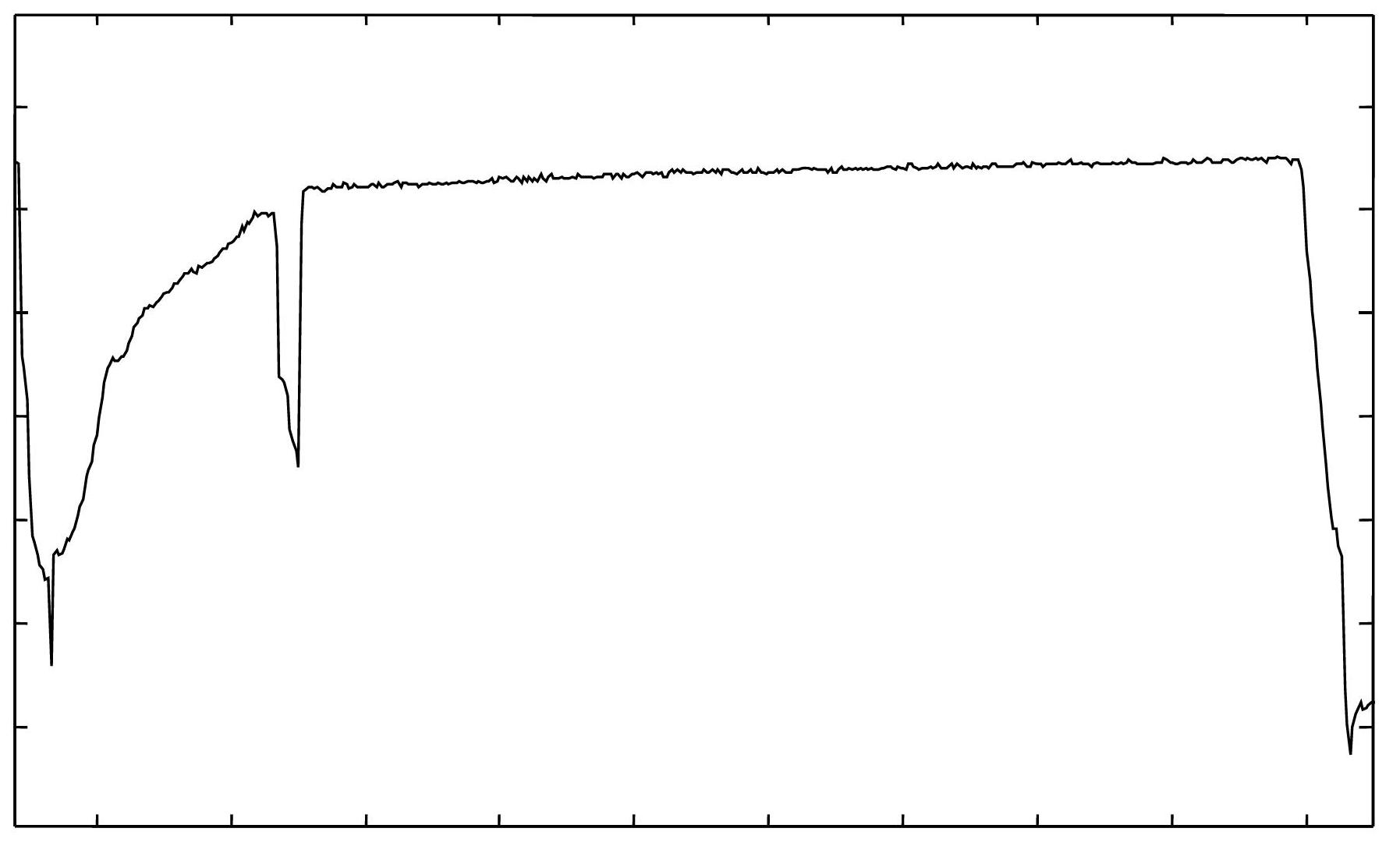
Chinese patent application 200910092596.1 introduces a method of monitoring road vehicles using a laser rangefinder or ultrasonic rangefinder placed vertically on the road surface, which can achieve the purpose of identifying the type of road vehicle and monitor the distance change point during identification. However, this patent The sampling rate of the method for vehicle identification is low, and the vehicle cannot be carefully screened; another shortcoming of this patent is that because this patent does not consider the influence of the speed of the vehicle on the sampling rate of the vehicle height point, the recognition rate of the vehicle type Very low, poor application effect

Method used


Image

  • Method for acquiring road information based on laser ranging node system
  • Method for acquiring road information based on laser ranging node system
  • Method for acquiring road information based on laser ranging node system

Examples


Embodiment Construction

[0046] In order to understand the technical content of the present invention more clearly, the following examples are given in detail.

[0047] see figure 1 As shown, it is a schematic diagram of the application mode of the node system adopted by the method for realizing road information collection based on the laser ranging node system of the present invention.

[0048] The system includes a plurality of laser ranging node devices 1 and a bayonet server 4 connected to each device 1. The node device 1 is erected on the upper gantry 2 of a lane on the road 6, and is connected to the bayonet server through a cable 5. 4. The laser ranging node device 1 includes a laser distance sensor and a data processor built in the laser distance sensor. The laser distance sensor is a large-angle laser transceiver distance sensor erected above a lane on the road, and the laser distance sensor is a large-angle laser transceiver distance sensor, such as figure 2 As shown, the large-angle las...


PUM


Abstract

The invention relates to a method for acquiring road information based on a laser ranging node system. A node device realizes laser ranging in a certain inclination mode, an internal data processor can recognize vehicle information according to related information of a distance value, accordingly, the functions of vehicle speed measurement, vehicle behavior trigger, vehicle contour tracing, vehicle flow counting and the like can be realized, and a bayonet server can acquire the road information according to the vehicle information of the laser ranging node device to release road service information and road supervision instructions. The method for acquiring the road information based on the laser ranging node system can be used for efficiently acquiring the road information, and can effectively overcome the shortcomings of complicated laying, low sampling rate, incapability of effectively identifying vehicle types and the like of a detection device in the prior art. Moreover, the method for acquiring the road information based on the laser ranging node system is simple and convenient in application, low in cost, excellent in application effect, fine in application expansibility and wide in application range.

Description

technical field [0001] The present invention relates to the technical field of traffic information collection methods, in particular to the technical field of traffic information collection methods using laser ranging equipment, and specifically refers to a method for realizing road information collection based on a laser ranging node system. Background technique [0002] Laser distance sensor (also known as laser range finder) is an instrument that uses laser to accurately measure the distance of the target. The laser distance sensor relies on the reflection of the target to identify: the sensor emits a pulsed laser to the target, the photoelectric element receives the laser pulse reflected by the target, and the time discrimination measures the pulse flight time of the laser beam from emission to reception, and the distance from the sensor to the target can be obtained. distance. The laser radar developed on the basis of the laser distance sensor can not only measure the ...

Claims


Application Information

Patent Timeline
Patent Type & Authority Applications(China)
IPC IPC(8): G08G1/04G08G1/052G01C3/00
Inventor 陈建永李万才江洪沈冬青李震宇梅林吴轶轩
Owner THE THIRD RES INST OF MIN OF PUBLIC SECURITY
Learn More