
Solar cell

A solar cell and electrode technology, applied in the field of solar cells, can solve the problems of increased resistance, loss of efficiency, and decreased photoelectric conversion efficiency of solar cells 300

Inactive Publication Date: 2012-09-12
AU OPTRONICS CORP
View PDF7 Cites 4 Cited by
  • Summary
  • Abstract
  • Description
  • Claims
  • Application Information

AI Technical Summary

Problems solved by technology

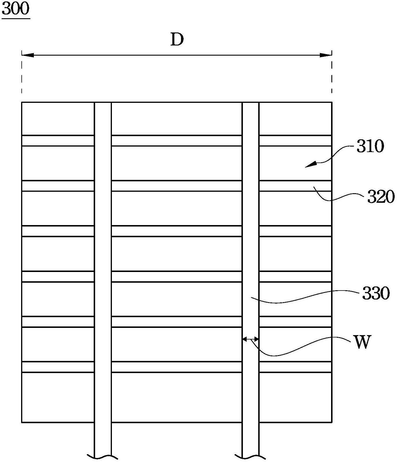
However, since each ribbon 330 has a width W respectively, two ribbons 330 will cover the light-receiving surface 310 with a width of 2W.
As a result, the light-facing surface 310 located under the two solder ribbons 330 cannot be irradiated with light, which reduces the photoelectric conversion efficiency of the solar cell 300
In order to increase the photoelectric conversion efficiency of the solar cell 300, however, it is easy to directly reduce the number of solder ribbons 330, but this will cause the carrier of the solar cell 300 to move longer on the finger electrode 320, Efficiency loss due to high resistance
Therefore, how to increase the photoelectric conversion efficiency of the solar cell 300 is a big challenge.

Method used


Image

  • Solar cell
  • Solar cell
  • Solar cell

Examples


Embodiment Construction

[0064] Hereinafter, multiple embodiments of the present invention will be disclosed with the accompanying drawings. For clear description, many practical details will be described in the following description. However, it should be understood that these practical details should not be used to limit the present invention. In other words, in some embodiments of the present invention, these practical details are unnecessary. In addition, in order to simplify the drawings, some well-known and conventional structures and elements will be shown in the drawings in a simple schematic manner.

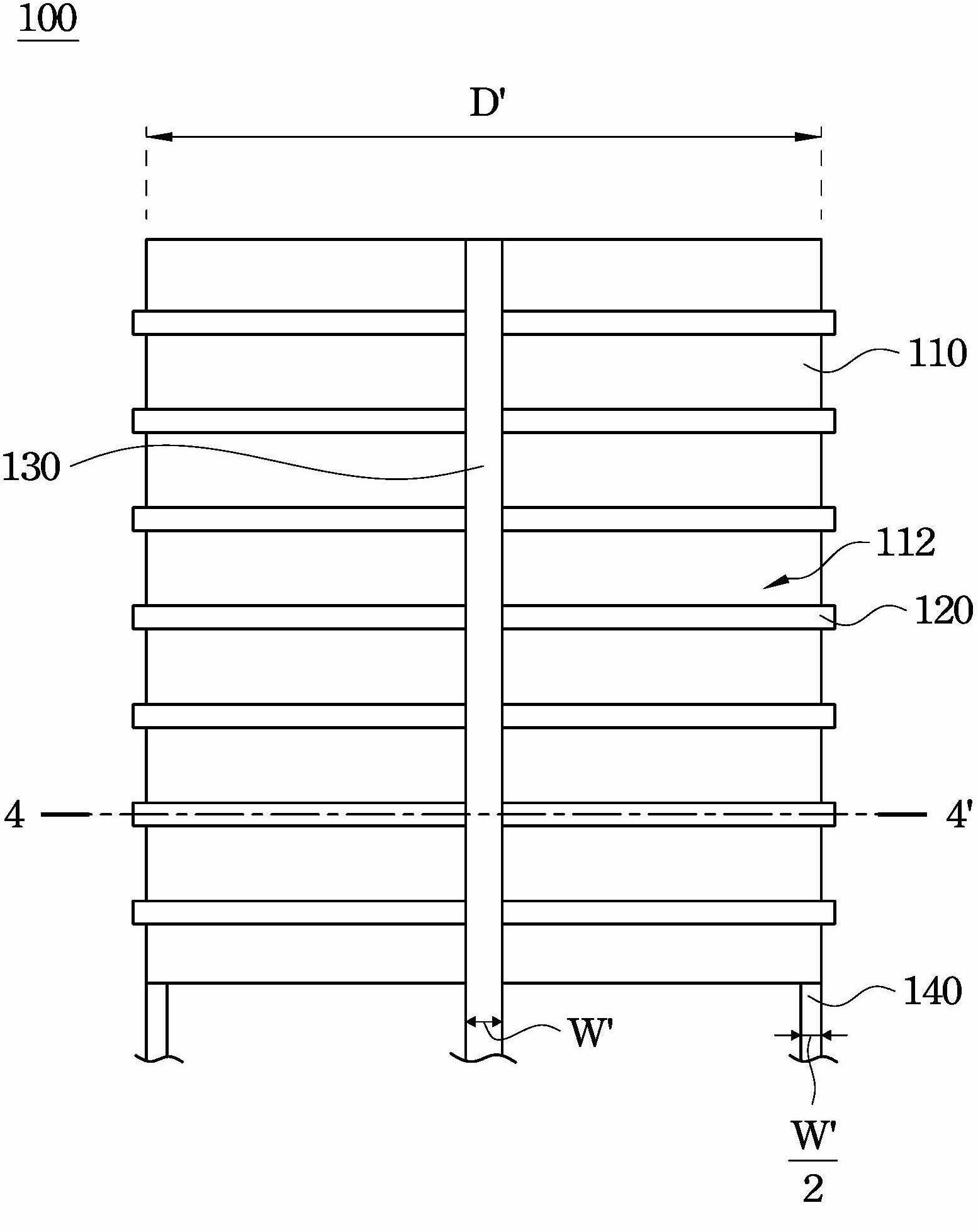
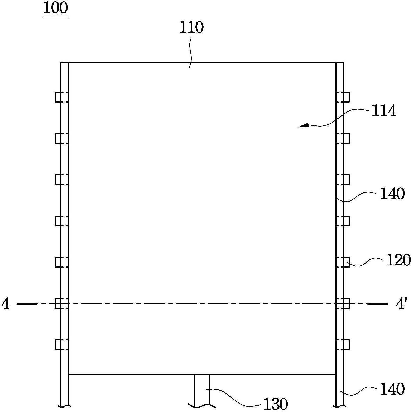
[0065] figure 2 A top view of a solar cell 100 according to an embodiment of the present invention is shown. image 3 show figure 2 Bottom view of the solar cell 100. Also see figure 2 versus image 3 , The solar cell 100 includes a body 110, a plurality of first finger electrodes 120, a first welding ribbon 130 and a second welding ribbon 140. The main body 110 has a first surface 112 and a s...


PUM


Abstract

The invention relates to a solar cell which comprises a main body, a plurality of first finger electrodes, a first solder strip and a second solder strip, wherein the main body is provided with a first surface and a second surface which are positioned on two opposite sides; the first finger electrodes are positioned on the first surface, and each first finger electrode is provided with an end which is bent and extends onto the second surface; the first solder strip is positioned on the first surface, and electrically connected with the first finger electrodes; and the second solder strip is positioned on the second surface, and electrically connected with the first finger electrodes. The solar cell provided by the invention can not increase the migration distance of the current carrier on the first finger electrodes, and can increase the area of the first surface of the solar cell irradiated by light rays, thereby enhancing the photoelectric conversion efficiency of the solar cell.

Description

Technical field [0001] The invention relates to a solar cell. Background technique [0002] Solar cells can convert light energy into electrical energy, and sunlight is the main source of light energy. Since solar cells do not generate greenhouse gases during the conversion process, a green energy environment can be achieved. In recent years, with the advancement and development of solar energy technology, the price of solar cells has fallen sharply, making solar cells more popular in the consumer market. For example, solar cells have been widely used in residential roofs and exterior walls of buildings, as well as various electronic products. [0003] figure 1 A plan view of a known solar cell 300 is shown. As shown in the figure, the solar cell 300 has a light-facing surface 310, and a plurality of finger electrodes 320 and solder ribbons 330 are formed on the light-facing surface 310. The welding ribbon 330 is located on the finger electrode 320 and is electrically connected...

Claims


Application Information

Patent Timeline
Patent Type & Authority Applications(China)
IPC IPC(8): H01L31/05H01L31/02H01L31/0224
CPCY02E10/50H01L31/022433H01L31/0504H01L31/02008
Inventor 刘书谦陈麒麟詹逸民
Owner AU OPTRONICS CORP
Learn More