Control device of electromagnetic brake

A technology of electromagnetic brakes and control devices, applied in the direction of controlling electromechanical brakes, control systems, electrical components, etc., can solve the problems of complex structure of the control system, poor anti-interference ability, brake malfunction, etc., and achieve simple circuit design and anti-interference Strong ability and low energy consumption

Inactive Publication Date: 2012-09-12
YANSHAN UNIV
View PDF6 Cites 20 Cited by
  • Summary
  • Abstract
  • Description
  • Claims
  • Application Information

AI Technical Summary

Problems solved by technology

[0007] The technical problem to be solved by the present invention is to provide a control device for an electromagnetic brake, so as

Method used


Image

  • Control device of electromagnetic brake
  • Control device of electromagnetic brake
  • Control device of electromagnetic brake

Examples


Embodiment Construction

[0036] The specific implementation manners of the present invention will be further described in detail below in conjunction with the accompanying drawings and embodiments. The following examples are used to illustrate the present invention, but are not intended to limit the scope of the present invention.

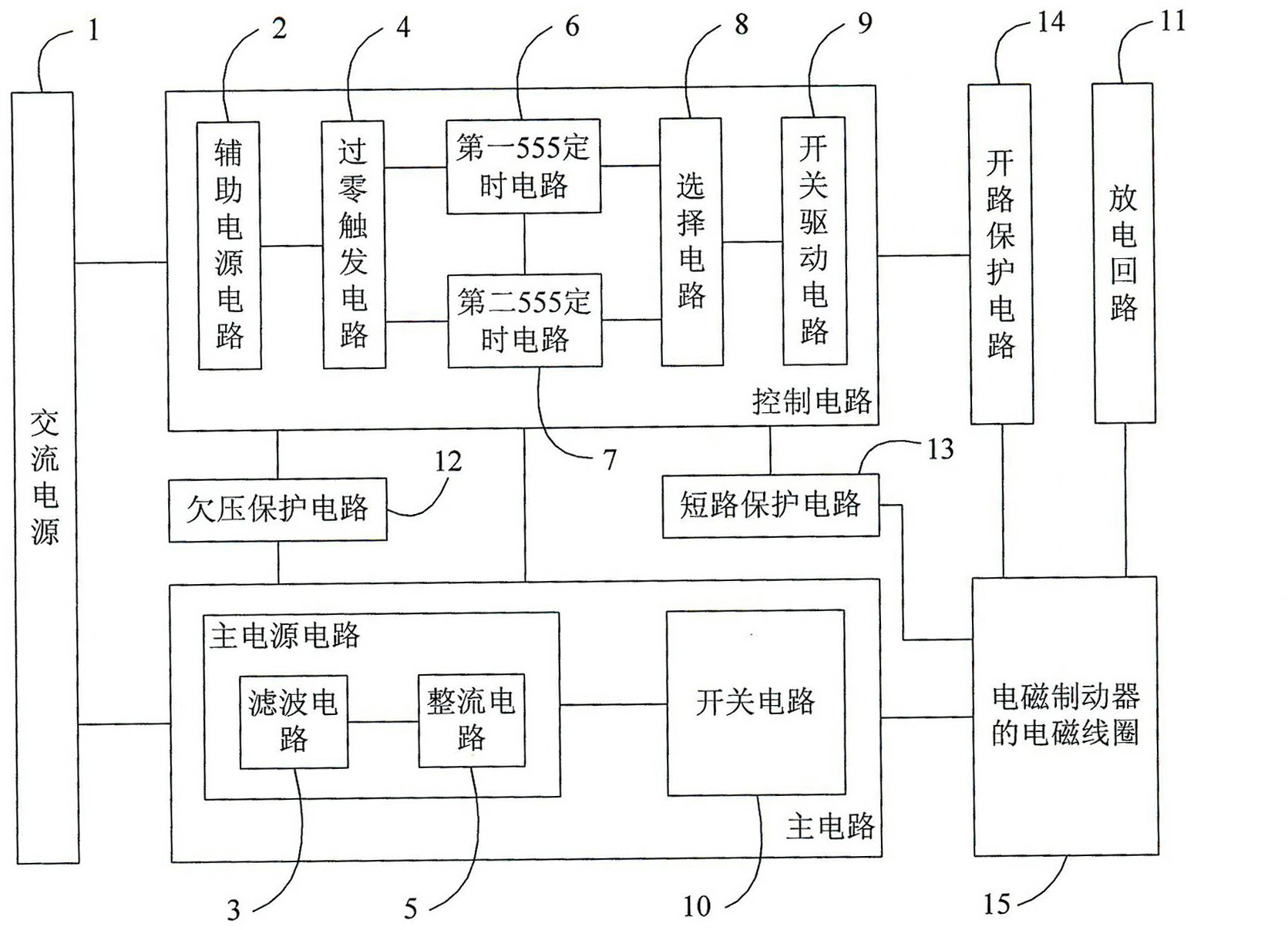
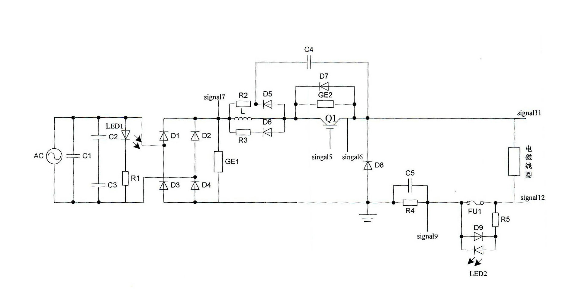
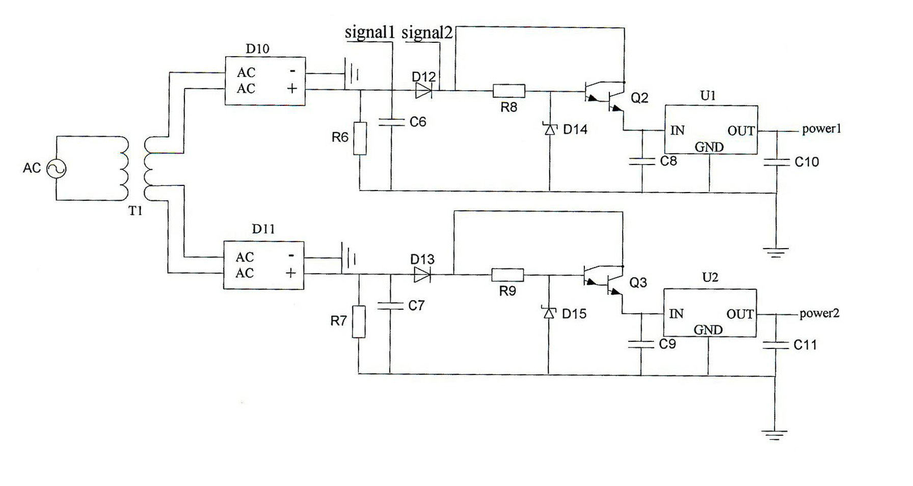
[0037] The invention adopts two monostable triggers composed of two 555 timers to control the conduction angle of the IGBT and then control the voltage at both ends of the electromagnetic brake coil through the transformation of the logic relationship of the logic gate circuit. The control device contains a zero-crossing trigger circuit with a feedforward function. When the input voltage of the control device changes, the zero-crossing trigger circuit can stabilize the voltage at both ends of the electromagnetic coil through the adjustment of its feedforward link; it also contains an efficient and rapid discharge The circuit can quickly release the energy in the electromag...


PUM


Abstract

The invention belongs to the technical field of switch control, and discloses a control device of an electromagnetic brake. The control device comprises a main circuit, a control circuit and a protection circuit. According to the invention, an IGBT (insulated gate bipolar translator) conduction angle is controlled by adopting two monostable triggers formed by two 555 timers via the logic relation conversion of a logic gate circuit, so as to further control the voltage at two ends of the coil of the electromagnetic brake. The control device comprises a zero passage trigger circuit having a feedforward action, and when the input voltage of the control device changes, the zero passage trigger circuit can stabilize the voltage at two ends of an electromagnetic coil via the adjustment of the feedforward link. The control device also comprises an efficient and rapid discharge circuit which can rapidly release energy in the coil of an electromagnet after outage, and also has the protection measures of low voltage protection, short circuit protection, open circuit protection and the like, so that the electromagnetic brake is safer and more stable and reliable in operation.

Description

technical field [0001] The invention belongs to the technical field of switch control, and particularly relates to a control device for an electromagnetic brake used for controlling the excitation state of an electromagnetic coil of an electromagnetic brake device such as a brake device of a dumper. Background technique [0002] Brakes are widely used in hoisting machinery, mining machinery, port equipment, construction machinery and various automation equipment in industrial production, and are an indispensable part of large mobile equipment. At present, domestic and foreign brakes are in the era of alternation between old and new. Old-fashioned brake electromagnets have disadvantages such as large starting and maintaining current, low power factor, large size, high failure rate, high energy consumption, and high noise; while hydraulic brakes have oil leakage. The risk of pollution, ranging from polluting the environment, resulting in waste of lubricating oil, and causing h...

Claims


Application Information

Patent Timeline
IPC IPC(8): H02P15/00
Inventor 卢志刚郝懿乐孟大伟陈少功罗雄
Owner YANSHAN UNIV
Why Eureka
Try Eureka