Check patentability & draft patents in minutes with Patsnap Eureka AI!

LED lamp fault detection system

A technology of LED lighting and fault detection, which is applied in lighting devices, lamp circuit layout, light sources, etc., can solve problems such as system cumbersomeness, multiple resources, and increase the difficulty of system maintenance, and achieve the effect of simplifying structure, reducing maintenance difficulty and cost

Inactive Publication Date: 2012-09-12
SICHUAN SUNFOR LIGHT
View PDF5 Cites 2 Cited by
  • Summary
  • Abstract
  • Description
  • Claims
  • Application Information

AI Technical Summary

Problems solved by technology

The number of current detection devices depends on the number of LED lamp bead loops in the lamp. If there are more LED lamp beads in the LED lighting control system, such as office lighting, square lighting / decoration, etc., there will be many fault detection devices. , which makes the system very cumbersome, consumes too many resources, and increases the difficulty of system maintenance

Method used


Image

  • LED lamp fault detection system
  • LED lamp fault detection system

Examples


Embodiment Construction

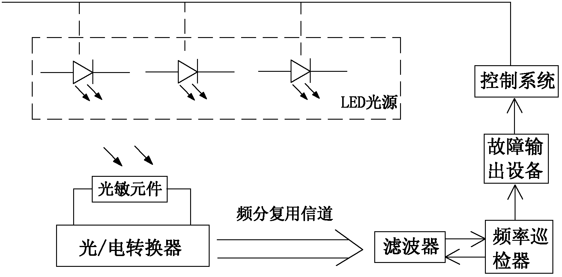
[0013] Such as figure 1 As shown, the fault detection system for LED lighting fixtures of the present invention includes an optical / electrical converter, the input end of the optical / electrical converter is connected with a photosensitive element, and the photosensitive element is a photoresistor or a photodiode. The optical / electrical converter is connected with the frequency patrol device through the frequency division multiplexing channel through the filter. The output end of the frequency patrol device is connected to the control system through the fault output device. When working, the control bus assigns different frequencies to each LED lamp bead, and the photosensitive element senses the different frequency light of each LED lamp bead and transmits it to the optical / electrical converter. The optical / electrical converter performs optical / electrical conversion on the input light of different frequencies, and transmits it to the filter through the frequency division mult...


PUM


Abstract

The invention relates to an LED lamp fault detection system which comprises a photoelectric converter. The photoelectric converter is connected with a frequency routing inspection device through a frequency multiplexing channel, and an output end of the frequency routing inspection device is connected to a control system through fault output equipment. By the LED lamp fault detection system, each LED lamp bead in a certain area can be subjected to fault detection without being provided with a fault detection device, the structure of an LED lamp system is simplified evidently, and maintenance difficulty and cost thereof is effectively reduced.

Description

technical field [0001] The invention relates to a fault detection system for LED lighting fixtures, and is particularly suitable for but not limited to a device for simultaneous fault detection of a plurality of LEDs with different frequencies. Background technique [0002] In the current LED dimming lighting system, usually use PWM (pulse width modulation) signal to control the LED driver, by changing the voltage V applied to the LED lamp bead LED and the current I flowing through the LED lamp bead LED To change the brightness of the LED lamp bead according to the turn-on time. Therefore, the brightness of the LED lamp bead is only with V LED and I LED The duty cycle D is related, and the duty cycle D=T ON / (T ON +T OFF ) T ON is the opening time, T OFF For the off time, the duty cycle D and V LED and I LED frequency is irrelevant. Therefore, the larger the duty cycle D, the brighter the LED; conversely, the smaller the duty cycle D, the darker the LED. [0003]...

Claims


Application Information

Patent Timeline
IPC IPC(8): H05B37/03
Inventor 田栋李东明何天兵
Owner SICHUAN SUNFOR LIGHT
Features
  • R&D
  • Intellectual Property
  • Life Sciences
  • Materials
  • Tech Scout
  • Unparalleled Data Quality
  • Higher Quality Content
  • 60% Fewer Hallucinations
Learn More