Device for storing gas under pressure

A technology of equipment and gas, which is applied in the field of storage equipment/systems, can solve problems such as the difficulty of gas leakage detection, and achieve the effect of flexible module design

Inactive Publication Date: 2012-09-12
NEL HYDROGEN AS
View PDF8 Cites 4 Cited by
  • Summary
  • Abstract
  • Description
  • Claims
  • Application Information

AI Technical Summary

Problems solved by technology

[0006] However, the system makes gas leak detection difficult
The system would allow gas leaks to permeate uncontrolled through the top of the pool, thus creating a potential risk of undetected explosive gas mixtures

Method used


Image

  • Device for storing gas under pressure
  • Device for storing gas under pressure
  • Device for storing gas under pressure

Examples


Embodiment Construction

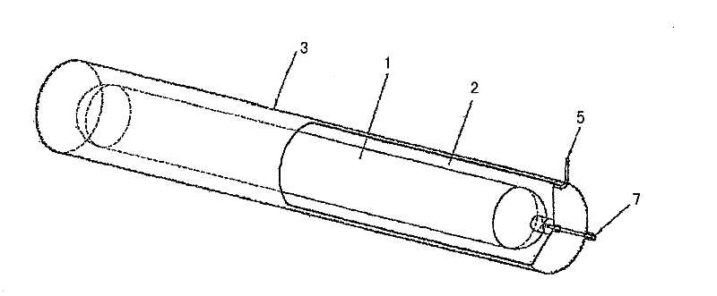
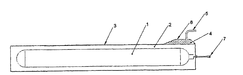
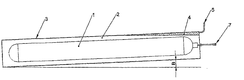
[0024] Now refer to figure 1 , The pressurized tank 1 is accommodated in the surrounding tank 3 in a jacketed tank configuration. An annular or surrounding space 2 is provided between the pressurized tank 1 and the surrounding tank 3 and is filled with a suitable fluid. The fluid may be water, glycol or any other suitable fluid with suitable properties such as inertness, stability, ability to absorb gas, etc. The fluid may also have appropriate compounds or additives to allow changing the color of the fluid, enhancing or reducing the conductivity of the fluid, or other properties that may assist the gas detection device in detecting gas leaks.

[0025] Since according to the invention only the annulus or space 2 between the inner and outer tanks is filled with fluid, the contact between the escaping combustible gases and air or some other gas occurs only in the pre-defined venting area 4, The ventilation area 4 is equipped with a ventilation tube 5 and a gas detection device...


PUM


Abstract

The present invention relates to a device for storing gas under pressure comprising an inner cylindrical pressure vessel (1), the pressure vessel (1) comprising pipe connection (7). According to the present invention, the device is characterized in that the inner cylindrical pressure vessel (1) is arranged inside an outer vessel (3), whereby a substantially annular space (2) is formed between the inner pressure vessel (1) and the outer vessel (3), wherein the annular space (2) between the inner pressure vessel (1) and the outer vessel (3) is filled with a fluid, the outer vessel (3) further comprising venting means (5) at or in the vicinity of the highest point (4, 6) of the outer vessel (3).

Description

technical field [0001] The present invention relates to a storage device / system for storing pressurized gas. The device is especially suitable for storing compressed gaseous hydrogen and can be connected to a hydrogen refueling system. The invention is also applicable to other gases such as hydrocarbons, which are usually stored for industrial purposes, for refueling vehicles or for heating purposes. Background technique [0002] Typically, gaseous hydrogen is stored in pressurized cylindrical tanks (pressure vessels) of various sizes. These barrels are either made of steel or a composite material comprising an airtight liner (usually metal or plastic) and a fiber envelope. Typically, the storage facility comprises several individual containers interconnected with gas conduits (gas supply conduit and gas discharge conduit). Typically, the containers are arranged in a rectangular pattern and are supported by a metal frame that holds the containers in place relative to each...

Claims


Application Information

Patent Timeline
Patent Type & Authority Applications(China)
IPC IPC(8): F17C1/00F17C13/08
CPCF17C1/00F17C13/084F17C2201/032F17C2201/035F17C2201/037F17C2201/054F17C2203/0604F17C2203/0617F17C2203/0639F17C2203/0658F17C2203/0663F17C2205/0111F17C2205/0134F17C2205/0138F17C2205/0142F17C2205/0149F17C2205/0352F17C2221/012F17C2221/014F17C2221/032F17C2223/0123F17C2223/0153F17C2223/035F17C2223/036F17C2227/0341F17C2227/0348F17C2227/0381F17C2227/0388F17C2250/0452F17C2250/0495F17C2260/015F17C2260/038F17C2260/04F17C2260/042F17C2270/0134F17C2270/0139F17C2270/0147F17C2270/0168Y02E60/32F17C13/08
Inventor 托尔吉尔·纳肯扬·舍林莱夫·卡雷·格龙斯塔德桑德拉·尼尔森奥德·斯塔莱·特韦特比若马尔·沃尔斯威克
Owner NEL HYDROGEN AS
Why Eureka
Try Eureka