Water body heater for aquarium creature culture and pet feeding

A technology for heaters and water bodies, applied in water heaters, fluid heaters, lighting and heating equipment, etc., can solve the problems of glass or ceramic tubes that are easily broken, low heat conduction efficiency, and limited use occasions, and achieve environmental protection Lightweight, avoid easy breakage, and increase the effect of contact area

Inactive Publication Date: 2012-09-19
SHENZHEN XING RISHENG INDAL
View PDF0 Cites 1 Cited by
  • Summary
  • Abstract
  • Description
  • Claims
  • Application Information

AI Technical Summary

Problems solved by technology

Due to its shape limitation, when the heater is working, only the outer surface of the cylinder is in contact with the surrounding medium for heat exchange, and the heat conduction efficiency is not high
At the same time, the cylindrical shape also limits the use occasions, and the glass tube or ceramic tube is easily broken, posing unsafe hazards

Method used


Image

  • Water body heater for aquarium creature culture and pet feeding
  • Water body heater for aquarium creature culture and pet feeding
  • Water body heater for aquarium creature culture and pet feeding

Examples


no. 1 example

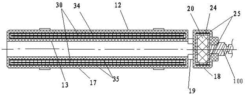
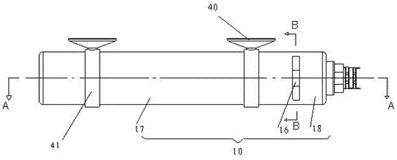
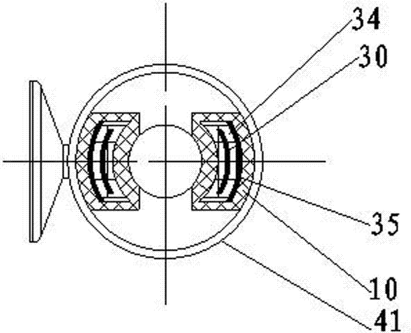
[0033] refer to Figure 1 to Figure 4 As shown, the housing 10 is a tubular body, including a first section of double-walled tubular body 17 for accommodating a heating element 30 and a second section of tubular body 18 with a built-in temperature control circuit assembly 20; in the first section of tubular body 17 The connecting section 19 between the second section of the tubular body 18 is provided with a radial channel 16, and the channel 16 communicates with the axial central cavity of the first section of the double-walled tubular body 17; the axial central cavity The cylindrical wall surface of the inner ring is the second heat exchange surface 13 , and the wall surface of the channel 16 is a part of the second heat exchange surface 13 .

[0034] The tubular casing includes two nested inner tubes and outer tubes, and has an annular bottom cover. The outer wall of the inner tube, the inner wall of the outer tube and the annular bottom cover form a sandwich container for...

no. 2 example

[0038] refer to Figure 5 to Figure 7 As shown, the shell 60 is in the shape of a hollow plate, and the front and rear sides of the plate-shaped shell 60 are respectively the first heat exchange surface 62 and the second heat exchange surface 63 .

[0039] The heating element 80 has a plate shape adapted to the cavity shape of the housing 60 . The heating element is in the shape of a flexible plate.

[0040] The heat conduction layer 85 is also a sheet-shaped aluminum or copper material adapted to the shape of the cavity of the plate-shaped casing 60 .

[0041] Between the heating body 80 and the heat conduction layer 85, an insulating layer 84 with two sides respectively attached to the heat generation body 80 and the heat conduction layer 85 is provided, and an insulating layer 84 is provided between the temperature control circuit assembly 70 and the heat conduction layer 85. An insulating layer 74 is also arranged between the layers 75, and its two sides are respectively...


PUM


Abstract

The invention discloses a water body heater for aquarium creature culture and pet feeding, which comprises shells (10 and 60) as well as temperature control circuit assemblies (20 and 70) and heating bodies (30 and 80) which are arranged in the shells (10 and 60). The heater is provided with at least two heat exchange surfaces, i.e. first exchange surfaces (12 and 62) and second heat exchange surfaces (13 and 63); the surfaces of the temperature control circuit assemblies (20 and 70) and the heating bodies (30 and 80) are respectively wrapped by insulation layers (24, 34, 74 and 84); and the surfaces of the insulation layers (24, 34, 74 and 84) are tightly stuck on heat conduction layers (25, 35, 75 and 85) which are tightly stuck on the inner walls of the shells (10 and 60). According to the two preferable embodiments in the technical scheme, the water body heater can be of a tube type or a plate type. The water body heater of any type has the advantages of being high in heat conduction efficiency, simple in structure, low in cost and safe and convenient to use.

Description

technical field [0001] The present invention relates to a fluid heater with a heat generating device, and more particularly to a portable, movable water body heater for aquaculture and keeping pets. Background technique [0002] The prior art water body heaters used for aquaculture and raising pets usually use alloy resistance wires as heating elements, and are equipped with temperature control circuit components to be placed in glass tubes or ceramic tubes, or wrapped with an insulating layer made of mica. Placed in a plastic tube to form a cylindrical heater. Due to its shape limitation, when the heater is working, only the outer surface of the cylinder is in contact with the surrounding medium for heat exchange, and the heat conduction efficiency is not high. At the same time, the cylindrical shape also limits the application occasions, and the glass tube or the ceramic tube is easily broken, which poses a potential safety hazard. Contents of the invention [0003] Th...

Claims


Application Information

Patent Timeline
IPC IPC(8): A01K63/06F24H1/00F24H9/18F24H9/20F24H9/00
CPCA01K63/065H05B3/80
Inventor 邓培星
Owner SHENZHEN XING RISHENG INDAL
Why Eureka
Try Eureka