Implantable bionic flexible pulsatile pump

A bionic flexible and implantable technology, applied in the direction of suction devices, can solve problems such as large blood flow resistance, achieve the effects of reducing damage, compact overall structure, and expanding the range of applicable people

Active Publication Date: 2012-09-19
心瓴上海医疗科技有限公司
View PDF9 Cites 7 Cited by
  • Summary
  • Abstract
  • Description
  • Claims
  • Application Information

AI Technical Summary

Problems solved by technology

Although the above design scheme reduces the volume of the pump body, the design of the blood pump inlet and outlet on both sides of the blood cavity is not conducive to the cooperation of the blood pump with the natural cardiovascular system after implantation in the body, resulting in greater blood flow resistance

Method used


Image

  • Implantable bionic flexible pulsatile pump
  • Implantable bionic flexible pulsatile pump
  • Implantable bionic flexible pulsatile pump

Examples


Embodiment Construction

[0025] The idea, specific structure and technical effects of the present invention will be further described below in conjunction with the accompanying drawings, so as to fully understand the purpose, features and effects of the present invention.

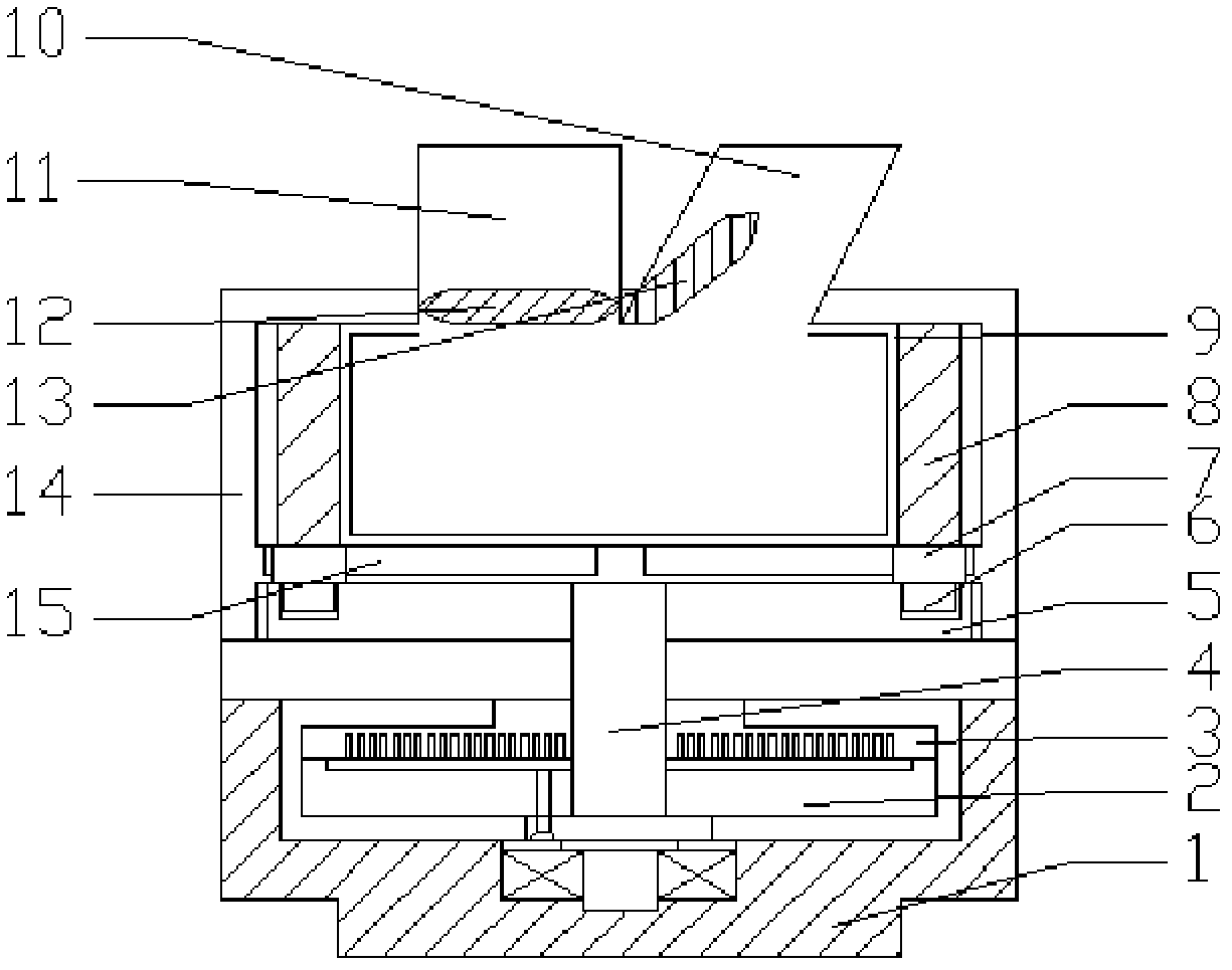
[0026] Such as figure 1 As shown, the implantable bionic flexible pulsating blood pump driven by an ultrasonic motor of the present invention includes: an ultrasonic motor, a grooved cam 5, a roller follower 6, a slider 7, an arc-shaped push plate 8, an elastic blood bag 9, Pump housing 14, circular partition 16 and linear guide rail 5.

[0027] Wherein, the ultrasonic motor includes a motor housing 1 , a stator 3 , a rotor 2 and an output shaft 4 . The rotor 2 and the stator 3 are coaxially in contact, the stator 3 is located above the rotor 2, and the output shaft 4 is connected with the rotor 2 by bolts to output power.

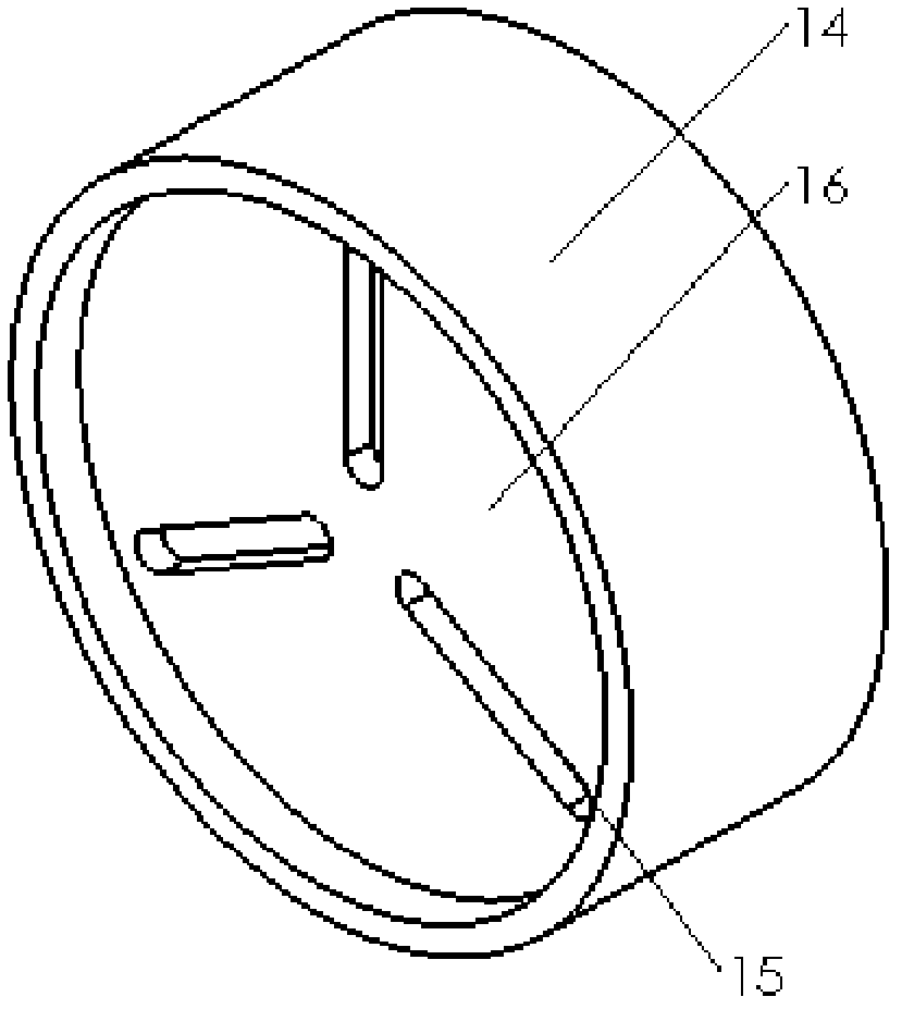
[0028] The axial isometric view of the pump housing 14 is as follows figure 2 shown. The circular parti...


PUM


Abstract

The invention discloses an implantable bionic flexible pulsatile pump driven by an ultrasonic motor. The pump comprises the ultrasonic motor, a groove cam, a roller follower, a slide block, an arc push plate, an elastic blood bag, a pump housing, a round separating plate and a linear guideway. According to The implantable bionic flexible pulsatile pump driven by the ultrasonic motor, the damage of blood pump to blood can be reduced effectively, the mounting location of the implantable bionic flexible pulsatile pump is not limited; the whole structure is compact, so that the volume of the pulsatile pump can be reduced effectively; and the implantability is added, so that the range of application suitable for the crowd is expanded.

Description

technical field [0001] The invention relates to a ventricular assist device in the technical field of medical instruments, in particular to an implantable bionic flexible pulsating blood pump driven by an ultrasonic motor. Background technique [0002] At present, heart disease has become one of the most important diseases affecting human health in the world. Mechanically assisted circulation is not only an effective method of cardiac assistance therapy, but also gradually developed into a permanent treatment for heart failure. Existing heart assist devices can be divided into centrifugal, axial flow and pulsatile blood pumps according to the blood supply mode. Both centrifugal and axial flow blood pumps need to use high-speed rotating blades. Because the shear stress generated by high-speed rotation has a strong destructive force on red blood cells and other blood cells, it is easy to form thrombus, cause stroke, multiple organ failure and other serious consequences. The...

Claims


Application Information

Patent Timeline
Patent Type & Authority Applications(China)
IPC IPC(8): A61M1/12
Inventor 杨明徐亮鹿存跃李世阳
Owner 心瓴上海医疗科技有限公司
Why Eureka
Try Eureka