Hydraulic precision leveling machine

A leveling machine, hydraulic technology, applied in the field of hydraulic precision leveling machine, can solve the problems of bending and deformation of leveling roller, oil cylinder fatigue, unbearable lower beam, etc., to avoid trouble of maintenance, uniform reaction force, not easy The effect of bending deformation

Active Publication Date: 2014-07-30
常州市中安机械制造有限公司
View PDF8 Cites 2 Cited by
  • Summary
  • Abstract
  • Description
  • Claims
  • Application Information

AI Technical Summary

Problems solved by technology

[0002] At present, most of the precision levelers in the prior art have the upper beam not moving, while the lower beam is lifted and lowered by an oil cylinder. For example, Chinese patent CN201644559U discloses a leveler, the upper beam is fixed on the column, and the lower beam can be lifted. Slidingly set on the column, there is an oil cylinder between the lower beam and the machine base, and the piston rod of the oil cylinder is used to move up and down to achieve the up and down movement of the lower beam. The disadvantage of this type of leveling machine is: when the oil cylinder is used for too long, the oil cylinder There will be fatigue phenomenon, it is difficult to bear the lower beam, making it very difficult to move the lower beam up and down, and when the leveler is working, because the oil cylinder has to bear the weight of the lower beam, the force applied to the lower beam will be uneven, affecting The leveling effect of the leveling machine on the plate; this type of leveling machine cannot maintain the gap between the upper beam and the lower beam, and cannot meet the requirements of different thicknesses of the plate; the leveling roller of this type of leveling machine will also occur during work. Bending deformation phenomenon, the leveling effect on the plate is not ideal, and it also increases its maintenance cost

Method used


Image

  • Hydraulic precision leveling machine
  • Hydraulic precision leveling machine
  • Hydraulic precision leveling machine

Examples


Embodiment Construction

[0017] In order to make the content of the present invention more clearly understood, the present invention will be further described in detail below based on specific embodiments and in conjunction with the accompanying drawings.

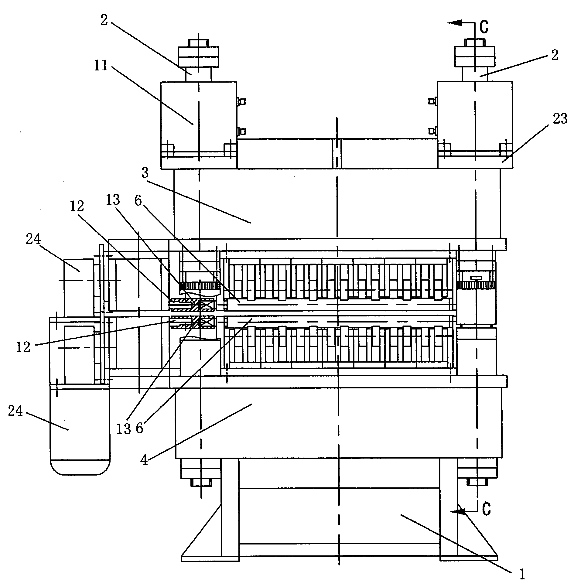
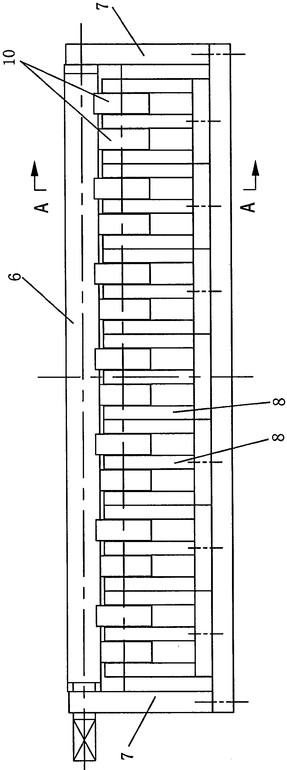
[0018] Such as Figure 1~6 As shown, a hydraulic precision leveler includes an upper roller group, a lower roller group, a load beam, a machine base 1 and four columns 2, the upper roller group and the lower roller group are respectively fixed with a power reduction device 24, and the load beam It consists of the upper beam 3 and the lower beam 4 fixed on the machine base 1, the upper roller group is fixedly connected with the upper beam 3, the lower roller group is fixedly connected with the lower beam 4, and the four columns 2 are respectively fixedly sleeved on the four corners of the lower beam 4 , the upper beam 3 is slidably set on the four columns 2 through the sliding sleeve 5, and the upper roller group and the lower roller group both incl...


PUM


Abstract

The invention discloses a hydraulic precision leveling machine which comprises an upper roller group, a lower roller group, a load bearing beam, a machine base and four upright posts, wherein the upper roller group and the lower roller group are respectively and fixedly provided with power decelerating devices, the load bearing beam is composed of an upper beam and a lower beam which is fixedly arranged on the machine base, the upper roller group is fixedly connected with the upper beam, the lower roller group is fixedly connected with the lower beam, the four upright posts are respectively and fixedly sheathed on four corners of the lower beam, and the upper beam can be movably sheathed on the four upright posts. Both the upper roller group and the lower roller group comprise a plurality of leveling rollers, wall plates, a plurality of support brackets, a plurality of fixing shafts and a plurality of support jockey pulleys, wherein the leveling rollers are arranged side by side and can be rotatablely supported on the wall plates on both sides, the fixing shafts are supported on the support brackets, and the support jockey pulleys can be rotatablely sheathed on the corresponding fixing shaft. The hydraulic precision leveling machine has the advantages of high leveling precision, simple structure and low manufacturing cost, and leveling requirements for plates with different thicknesses can be satisfied.

Description

technical field [0001] The invention relates to a hydraulic precision leveler, which belongs to the technical field of mechanical equipment. Background technique [0002] At present, most of the precision levelers in the prior art have the upper beam not moving, while the lower beam is lifted and lowered by an oil cylinder. For example, Chinese patent CN201644559U discloses a leveler, the upper beam is fixed on the column, and the lower beam can be lifted. Slidingly set on the column, there is an oil cylinder between the lower beam and the machine base, and the piston rod of the oil cylinder is used to move up and down to achieve the up and down movement of the lower beam. The disadvantage of this type of leveling machine is: when the oil cylinder is used for too long, the oil cylinder There will be fatigue, and it is difficult to bear the lower beam, making it very difficult to move the lower beam up and down. Moreover, when the leveler is working, because the oil cylinder...

Claims


Application Information

Patent Timeline
Patent Type & Authority Patents(China)
IPC IPC(8): B21D1/02
Inventor 周锋
Owner 常州市中安机械制造有限公司
Why Eureka
Try Eureka