Stamping system for cut materials

A stamping device and automatic feeding technology, which is applied in the field of punching and cutting processing, can solve the problems of low machine tonnage and precision requirements, shortened product life, and waste, so as to meet product requirements, reduce development investment, and reduce cost input. Effect

Inactive Publication Date: 2012-09-19
KUNSHAN XINTAILI PRECISION COMPONENTS CO LTD
View PDF4 Cites 3 Cited by
  • Summary
  • Abstract
  • Description
  • Claims
  • Application Information

AI Technical Summary

Problems solved by technology

[0002] At this stage, with the acceleration of the upgrading of electronic products, the supporting parts are polarized. Some standard parts need to develop high-precision, high-efficiency and long-life molds due to their high output and long life; while other non-standard parts Due to the faster update speed and shorter product life, molds and equipment with lower development costs are required to reduce product development costs and production costs. The future development of such products will also tend to be low-cost, small-batch, and fast-development models
[0003] At present, the stamping parts of many electronic products, especially the secondary stamping and cutting parts stamping, do not require high tonnage and precision of the machine, and the stamping machine cannot complete the feeding action of the non-flat sheet material. To complete this type of stamping, it is necessary Configure the corresponding equipment, which increases the product development cost, and the use of ordinary stamping machines is also a waste of such products

Method used


Image

  • Stamping system for cut materials
  • Stamping system for cut materials

Examples


Embodiment Construction

[0018] The preferred embodiments of the present invention will be described in detail below in conjunction with the accompanying drawings, so that the advantages and features of the present invention can be more easily understood by those skilled in the art, so as to define the protection scope of the present invention more clearly.

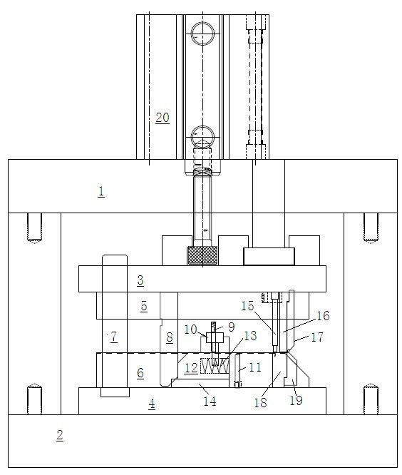
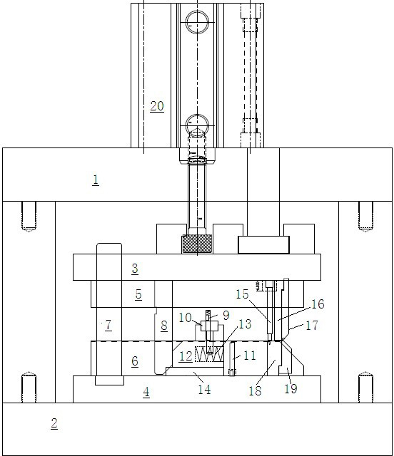
[0019] see figure 1 , the embodiment of the present invention includes:

[0020] A stamping system for material cutting, comprising: a stamping device and a power device.

[0021] The power unit includes a cylinder 20 and an electric system to provide power to the stamping device.

[0022] The stamping device includes an upper mold base 1, a lower mold base 2, an upper mold backing plate 3, a lower mold backing plate 4, an upper template 5, a lower template 6, a guide post 7, a slotting knife 8, a hook pin 9, a hook material Pin seat 10, limit pin 11, slide block 12, reset device 13, cushion block 14, positioning pin 15, pressing material punch...


PUM


Abstract

The invention discloses a stamping system for cut materials. The stamping system comprises a stamping device and a power device for supplying power to the stamping device, wherein the power device comprises an air cylinder and an electric power device, and the two power devices work in a mutually switching manner. According to the stamping system for the cut materials, disclosed by the invention, a stamping force is provided through air pressure, the equipment requirements are low, the mounting/dismounting is convenient, air cylinders of different types can be equipped according to the needs of products, and the stamping system can be switched into electric power control operation as required.

Description

technical field [0001] The invention relates to the field of punching processing, in particular to a material cutting punching system. Background technique [0002] At this stage, with the acceleration of the upgrading of electronic products, the supporting parts are polarized. Some standard parts need to develop high-precision, high-efficiency and long-life molds due to their high output and long life; while other non-standard parts Due to the faster update speed and shorter product life, molds and equipment with lower development costs are required to reduce product development costs and production costs. The future development of such products will also tend to be low-cost, small-batch, and fast-development models. [0003] At present, the stamping parts of many electronic products, especially the secondary stamping and cutting parts stamping, do not require high machine tonnage and precision, and the stamping machine cannot complete the feeding action of non-flat strips....

Claims


Application Information

Patent Timeline
Patent Type & Authority Applications(China)
IPC IPC(8): B21D28/02B21D28/14B21C51/00
Inventor 张晓亮刘建平
Owner KUNSHAN XINTAILI PRECISION COMPONENTS CO LTD
Why Eureka
Try Eureka