
Device for removing oil slick from turbid circulating water and recovering circulating water in aluminum processing industry

A technology of turbid circulating water and recovery device, which is applied in the direction of grease/oily substance/float removal device, water/sewage multi-stage treatment, water/sludge/sewage treatment, etc. , Isolate the problems of high water content of oil slick and incomplete separation of oil and water, and achieve the effect of good benefit prediction, simple facilities and water saving.

Active Publication Date: 2012-09-19
CHINA NERIN ENG
View PDF2 Cites 1 Cited by
  • Summary
  • Abstract
  • Description
  • Claims
  • Application Information

AI Technical Summary

Problems solved by technology

However, the first method has disadvantages: because the oil in the system is floating grease, the oil layer is distributed above the liquid level, while in the conventional turbid circulating water system, the suction bell of the circulating water pump is submerged by the water body, and it is impossible to extract the oily water body, so Oil removal filters used in turbid circulating water systems often fail to function
The second method has disadvantages: only the oil trap is used, the amount of isolated oil and water cannot be controlled, the water content of the isolated oil slick is high, and the oil and water cannot be completely separated, which will bring pressure to the subsequent oil collection facilities
The defect of the third method is: when the oil content of the turbid circulating water is within the range required by the process, the oil scraping and oil collection equipment will also discharge the circulating water that meets the water quality requirements, resulting in an increase in the amount of fresh water replenished by the circulating water, and Incomplete oil-water separation

Method used


Image

  • Device for removing oil slick from turbid circulating water and recovering circulating water in aluminum processing industry
  • Device for removing oil slick from turbid circulating water and recovering circulating water in aluminum processing industry
  • Device for removing oil slick from turbid circulating water and recovering circulating water in aluminum processing industry

Examples


Embodiment 1

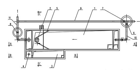
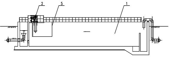
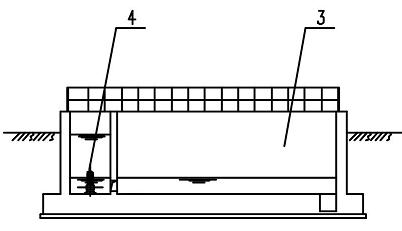
[0020] (1) Under normal working conditions, valve 7 is closed, valve 6 and valve 8 are opened, and the turbid circulating water passes through the grease trap 1 and then flows to the turbid circulating water return pool. An oil baffle plate 5 is set in the grease trap 1 to block the floating oil in the grease trap 1. The oil skimmer 2 selects an oil skimmer or an oil skimmer belt with a large or small oil skimming capacity, an oil skimmer or an oil skimmer belt according to the demand 2 is arranged on the top of the grease trap 1, and the oil skimmer or oil skimmer belt 2 works to collect floating oil into the oil collection tank 3.

[0021] (2) A water seal is set at the bottom of the oil collecting tank 3, and the depth of the water seal is ≥500mm, and a submersible pump 4 is installed in one end of the oil collecting tank 3, and the other end of the oil collecting tank 3 is in the middle of the pool body where the submersible pump 4 is placed A partition wall is provided, a...


PUM


Abstract

The invention relates to a device for removing oil slick from turbid circulating water and recovering circulating water in the aluminum processing industry. The device comprises an oil trap, an oil skimming device, an oil collecting pool and a submersible pump, wherein the oil trap is used for primary separation between turbid circulating water and oil slick; the oil skimming device is used for taking the oil slick out of water and transferring the oil slick to the oil collection pool; the oil collecting pool is used for secondary oil-water separation; and the submersible pump is used for recovering circulating water subjected to secondary oil-water separation to the oil trap. Through twice oil-water separation, the device has the advantages that the oil slick content of the turbid circulating water is reduced efficiently; and under the premise that the water quality of the turbid circulating water meets process requirements, the consumption of circulating water cannot be increased due to the collection of oil slick. Therefore, the purposes of saving circulating water and complementing new water are achieved.

Description

technical field [0001] The patent of the present invention relates to turbid circulating water in the aluminum processing industry, in particular to a process device for removing slick oil from turbid circulating water and recycling water. Background technique [0002] The turbid circulating water in the aluminum processing industry is used to cool the casting machine crystallizer and aluminum ingot, and the hydraulic cylinder of the casting machine is soaked in the cooling water in the casting well for a long time. The oil content brought into the turbid circulating water by the hydraulic rod during normal operation is about 1ml / m 3 , if there is oil leakage in the hydraulic cylinder, the floating oil content in the turbid circulating water can reach 25 ml / m 3 , and the processing technology requires that the oil content in the turbid circulating water should be controlled at 5ml / m 3 the following. If the oil content of the turbid circulating water exceeds the standard,...

Claims


Application Information

Patent Timeline
IPC IPC(8): C02F9/02C02F1/40
Inventor 刘钰畴何小英刘志荣刘志刚熊鸣魏巍
Owner CHINA NERIN ENG
Learn More