Air intake manifold with auxiliary resonant cavity

A technology of intake manifold and resonant cavity, which is applied in combustion air/combustion-air treatment, internal combustion piston engine, engine components, etc. The effect of short cycle and low cost

Inactive Publication Date: 2012-09-19
CHERY AUTOMOBILE CO LTD
View PDF6 Cites 4 Cited by
  • Summary
  • Abstract
  • Description
  • Claims
  • Application Information

AI Technical Summary

Problems solved by technology

[0003] The invention designs a sub-resonant cavity intake manifold, which solves the technical problem that the external characteristic performance of the natural aspirated gasoline engine cannot avoid a decline in a certain speed range, which is due to the intake manifold of the naturally aspirated engine. Due to gas resonance, at this stage, the performance loss can only be compensated by optimizing the length or pipe diameter of the intake manifold.

Method used


Image

  • Air intake manifold with auxiliary resonant cavity
  • Air intake manifold with auxiliary resonant cavity
  • Air intake manifold with auxiliary resonant cavity

Examples


Embodiment Construction

[0019] Combine below Figure 1 to Figure 4 , the present invention is further described:

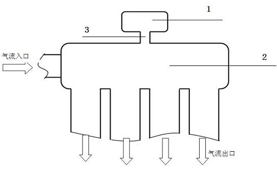
[0020] Such as figure 1 As shown, a secondary resonant cavity intake manifold is provided with a main resonant cavity 1 and a secondary resonant cavity 2 on the intake manifold. The primary resonant cavity 1 has an airflow inlet and an airflow outlet. Cavity 2 is connected. The sub-resonant chamber 2 is only connected to the main resonant chamber 1, so within a certain speed range of the engine, the resonance energy will be increased and the charging efficiency will be improved, but the charging efficiency at other speeds will not be affected.

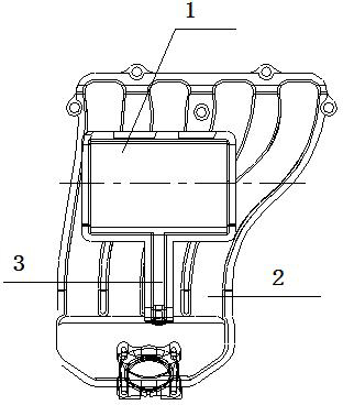
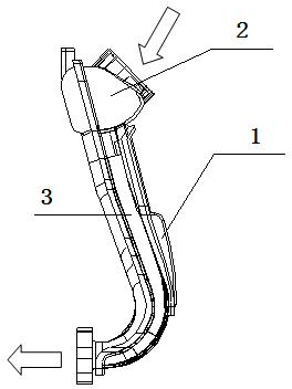
[0021] Such as figure 2 with image 3 As shown, changing the volume of the sub-resonator, the length and diameter of the connecting channel between the sub-resonator and the main resonator according to the performance requirements of a certain speed of the engine does not require a large-scale change in the design of the intake manifold to i...


PUM


Abstract

The invention relates to an air intake manifold with an auxiliary resonant cavity, which is characterized in that a main resonant cavity (1) and the auxiliary resonant cavity (2) are arranged on the air intake manifold, wherein the main resonant cavity (1) provided with an airflow inlet and an airflow outlet is further communicated with the auxiliary resonant cavity (2). The air intake manifold has the advantages that according a Helmholtz principle, the auxiliary resonant cavity is added to the air intake manifold of the best length, so that the resonant energy within a certain rotating speed range and the air intake quantity of an engine is increased, the resonant energy and the air charge efficiency are improved, and the air charge quantity required by other rotating speeds is not influenced.

Description

technical field [0001] The invention relates to an intake manifold, in particular to an intake manifold with a sub-resonance cavity for a naturally aspirated gasoline engine. Background technique [0002] Due to the influence of the length and pipe diameter of the intake system, the charging efficiency also changes drastically in the wide operating speed range of the naturally aspirated gasoline engine. According to the research and test results, under the condition of a certain length of the intake manifold, the charging efficiency will inevitably decrease in a certain speed range due to the difference of the engine speed frequency. Because of the influence of intake resonance, it is impossible to form a high-pressure area at the intake valve within a certain speed frequency, and it is impossible to use resonance to improve the charging efficiency within this speed range. To solve this kind of situation, a combination of multiple sets of intake manifold lengths and pipe di...

Claims


Application Information

Patent Timeline
Patent Type & Authority Applications(China)
IPC IPC(8): F02M35/104F02B29/02
CPCY02T10/146Y02T10/12
Inventor 陈伟国王伟
Owner CHERY AUTOMOBILE CO LTD
Why Eureka
Try Eureka