Vacuum pump with special-shaped cavity

A vacuum pump, special-shaped cavity technology, applied in the direction of pumps, pump components, rotary piston pumps, etc., to achieve the effect of high volumetric efficiency, simple structure, and small number of parts

Inactive Publication Date: 2012-09-19
NINGBO YINZHOU FUCHUN PRECISION CASTING
View PDF7 Cites 3 Cited by
  • Summary
  • Abstract
  • Description
  • Claims
  • Application Information

AI Technical Summary

Problems solved by technology

[0003] With the development of modern industrial technology, the performance requirements and economic requirements for vacuum pumps such as working efficiency, vacuum degree, pressure range, vibration and noise, reliability, wo...

Method used


Image

  • Vacuum pump with special-shaped cavity
  • Vacuum pump with special-shaped cavity
  • Vacuum pump with special-shaped cavity

Examples


Embodiment Construction

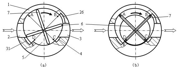
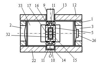
[0043] Reference Figure 1 to Figure 7 . The special-shaped cavity vacuum pump of the present invention includes a stator 1 with a special-shaped cylindrical inner cavity, an inlet 2, an outlet 3, a first unloading slot 4, a second unloading slot 26, and a pressure balance slot 31, and a stator 1 installed on both ends of the stator 1. The upper cover plate 12 and the lower cover plate 22 constitute a sealed cavity, and a rotor is installed in the sealed cavity.

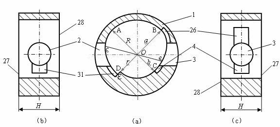
[0044] The special-shaped cylindrical cavity of the stator 1 is composed of a quarter arc surface AB, a transition arc surface BC, a quarter arc surface CD, a turning plane DE, and a limit curved surface EA in sequence; a quarter arc surface The surface AB and the quarter arc surface CD are coaxial, and the common axis is O (see figure 2 , image 3 ); The center of curvature of the B and C ends of the transition arc BC is located on the common axis O of the quarter arc surface AB and the quarter arc surface CD; the po...


PUM


Abstract

The invention discloses a vacuum pump with a special-shaped cavity; the vacuum pump comprises a stator and a rotor; wherein the stator is a cylinder body provided with a special-shaped cylindrical-surface inner cavity, an inlet and an outlet; the special-shaped cylindrical-surface inner cavity is formed by two arc surfaces and two non-arc surfaces; the rotor is formed by a rotor body and two pairs of combination slide plates; the rotor body is a circular cylinder body provided with a transmission shaft, a centering shaft and a crossed guide groove; the two pairs of combination slide plates are vertically arranged in the guide groove; a cover plate is a flat plate provided with a bearing hole; the two end faces of the stator are matched with the cover plate to form into a sealing cavity; the rotor is matched with the bearing hole on the cover plate by the transmission shaft and the centering shaft; the external drive couple drives the rotor to rotate by the transmission shaft. When the rotor rotates, the combined arc surface of the special-shaped cylindrical-surface inner cavity matches with the rotor to control the two pairs of combination slide plates to slide alternatively to intake air through the inlet and press air out through the outlet, thereby forming negative pressure in the inlet area.

Description

Technical field [0001] The invention relates to a special-shaped cavity vacuum pump, belonging to the technical field of fluid machinery and vacuum. Background technique [0002] A vacuum pump is a device that generates and maintains a thin gas state below the atmospheric pressure of the environment in a closed space. It has a wide range of applications in chemical, petroleum, pharmaceutical, food, metallurgy, machinery, paper, electronics, plastics, ceramics and other fields. According to the working principle, there are two basic types of vacuum pumps: gas delivery pump and gas trapping pump. Most of the vacuum pumps actually used are gas delivery pumps, including Roots vacuum pumps, rotary vane vacuum pumps, fixed vane vacuum pumps, liquid ring (water ring) vacuum pumps, dry vacuum pumps, reciprocating vacuum pumps, slide valve vacuum pumps, molecular vacuum pumps, Water jet vacuum pump, gas jet pump, diffusion pump, etc. [0003] With the development of modern industrial tech...

Claims


Application Information

Patent Timeline
IPC IPC(8): F04C18/344F04C29/00
Inventor 鲁阳高文通吕荣坤雷华
Owner NINGBO YINZHOU FUCHUN PRECISION CASTING
Why Eureka
Try Eureka