
Accelerated life test circuit and test method of power electronic device

A technology for power electronic devices and test circuits, applied in the field of power cycle life test circuits, can solve the problems of high manufacturing cost, inability to accurately detect the time when the gate leads are broken or falling off, and large time errors.

Active Publication Date: 2012-09-19
INST OF ELECTRICAL ENG CHINESE ACAD OF SCI
View PDF2 Cites 16 Cited by
  • Summary
  • Abstract
  • Description
  • Claims
  • Application Information

AI Technical Summary

Problems solved by technology

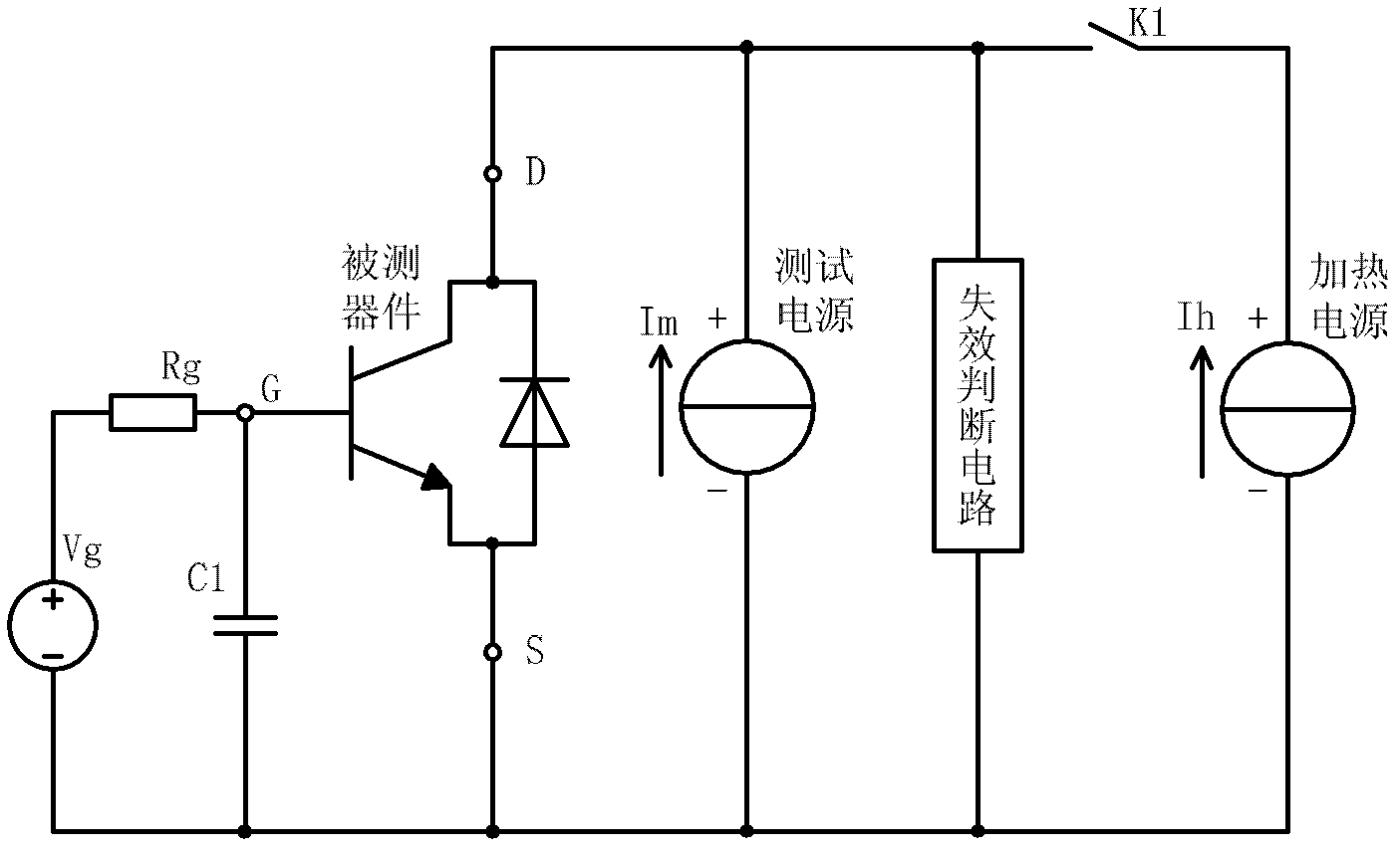
In order to make the chip junction temperature of the device under test rise to a higher temperature during the short period of time when the switch K1 is closed (usually within 10 seconds), the required heating current Ih will be very large, so based on the traditional method The power cycle test equipment has to be equipped with a heating power supply that can output a large current. However, for testing some high-power power electronic devices, the required heating current often reaches thousands of amperes. In order to obtain such a large output current, it has to be Dozens of power supplies are used in parallel, and the equipment manufacturing cost is very high
[0007] Second, the traditional method cannot accurately detect the time when the gate lead breaks or falls off
It can be seen that there is a large time error from the gate lead breaking or falling off to the failure judgment circuit making a fault judgment, that is, the traditional power cycle test method has defects in the fault judgment of the gate lead

Method used

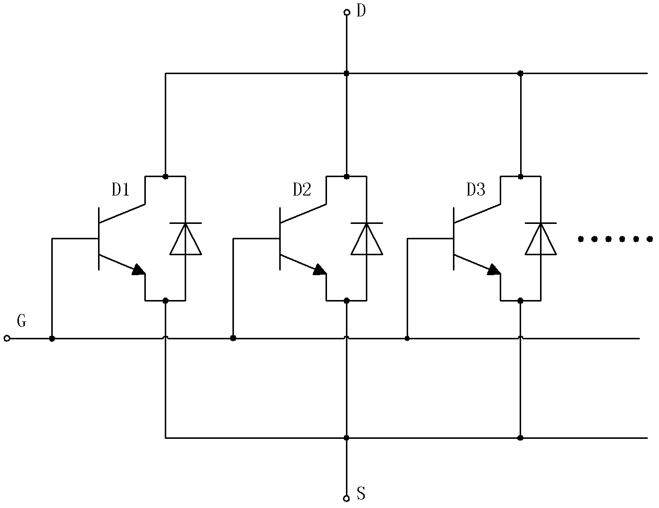

Image

  • Accelerated life test circuit and test method of power electronic device
  • Accelerated life test circuit and test method of power electronic device
  • Accelerated life test circuit and test method of power electronic device

Examples


Embodiment Construction

[0025] The present invention will be further described below in conjunction with the accompanying drawings and specific embodiments.

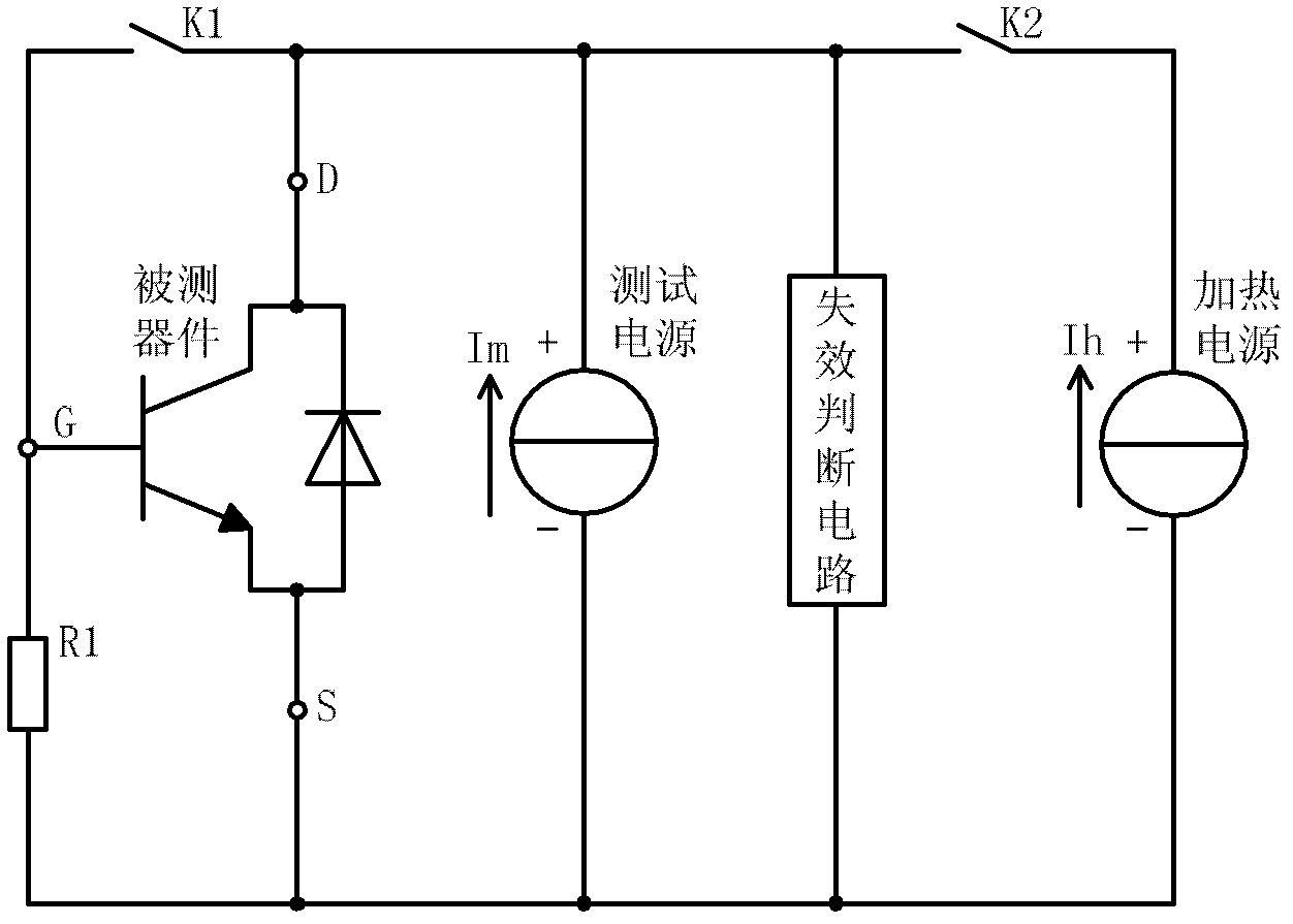
[0026] Such as image 3 As shown, the present invention includes a discharge resistor R1 for gate charge discharge, a first switch K1 for switching the state of the device under test, a second switch K2 for cutting off or enabling the heating current, a constant current test power supply for providing a stable test current, A failure judgment circuit for conduction voltage drop measurement and failure judgment, and a constant current heating power supply for heating current.

[0027] Such as image 3As shown, in the accelerated life test circuit for power electronic devices of the present invention, one end of the first switch K1 is connected to the drain D of the device under test, and the other end of the first switch K1 is connected to the grid G ​​of the device under test; the discharge resistor R1 One end of the discharge resistor R1 is ...


PUM


Abstract

The invention discloses an accelerated life test circuit of a power electronic device. One end of a first switch (K1) is connected with a drain (D) of a device to be tested, and the other end of the first switch (K1) is connected with a gate (G) of the device to be tested; one end of a discharge resistor (R1) is connected with the gate (G) of the device to be tested, and the other end of the discharge resistor (R1) is connected with a source (S) of the device to be tested; a positive electrode of a constant current test power supply is connected with the drain (D) of the device to be tested, and a negative electrode of the constant current test power supply is connected with the source (S) of the device to be tested; two input ends of a failure judgment circuit are respectively connected with the positive and negative electrodes of the test power supply; one end of a second switch (K2) is connected with the drain (D) of the device to be tested, and the other end of the second switch (K2) is connected with the positive electrode of a constant current heating power supply; and the negative electrode of the constant current heating power supply is connected with the source (S) of the device to be tested.

Description

technical field [0001] The invention relates to a power cycle life test circuit and a test method of power electronic devices. Background technique [0002] Among the concerns of modern power electronics packaging, the connection reliability of various materials is a major issue. Due to the different thermal expansion coefficients of various packaging materials, the temperature fluctuation caused by the switching loss and on-state loss of the semiconductor chip during the application of the device, or the change of the ambient temperature, will cause such as the bonding wire falling off, the welding layer Fatigue failure problems such as cracks. In order to test the reliability of the device package, accelerated testing methods such as thermal cycle test (passive cycle test) and power cycle test (active cycle test) are usually used in the industry, in which power cycle can more realistically simulate the actual heating mechanism of the chip: pass Control the output of the ...

Claims


Application Information

Patent Timeline
Patent Type & Authority Applications(China)
IPC IPC(8): G01R31/00G01R31/02
Inventor 张瑾仇志杰
Owner INST OF ELECTRICAL ENG CHINESE ACAD OF SCI
Learn More