Pulse laser distance measuring method

A pulsed laser ranging and pulsed laser technology, applied in measurement devices, radio wave measurement systems, electromagnetic wave re-radiation, etc. Cost and complexity reduction

Inactive Publication Date: 2012-09-19
BEIHANG UNIV
View PDF0 Cites 35 Cited by
  • Summary
  • Abstract
  • Description
  • Claims
  • Application Information

AI Technical Summary

Problems solved by technology

This method has a simple circuit structure and is easy to implement, but it needs to measure the error compensation curve in advance, fit the error compensation curve or establish an error compensation table, which increases the complexity of the pulse laser ranging method

Method used


Image

  • Pulse laser distance measuring method
  • Pulse laser distance measuring method
  • Pulse laser distance measuring method

Examples


Embodiment Construction

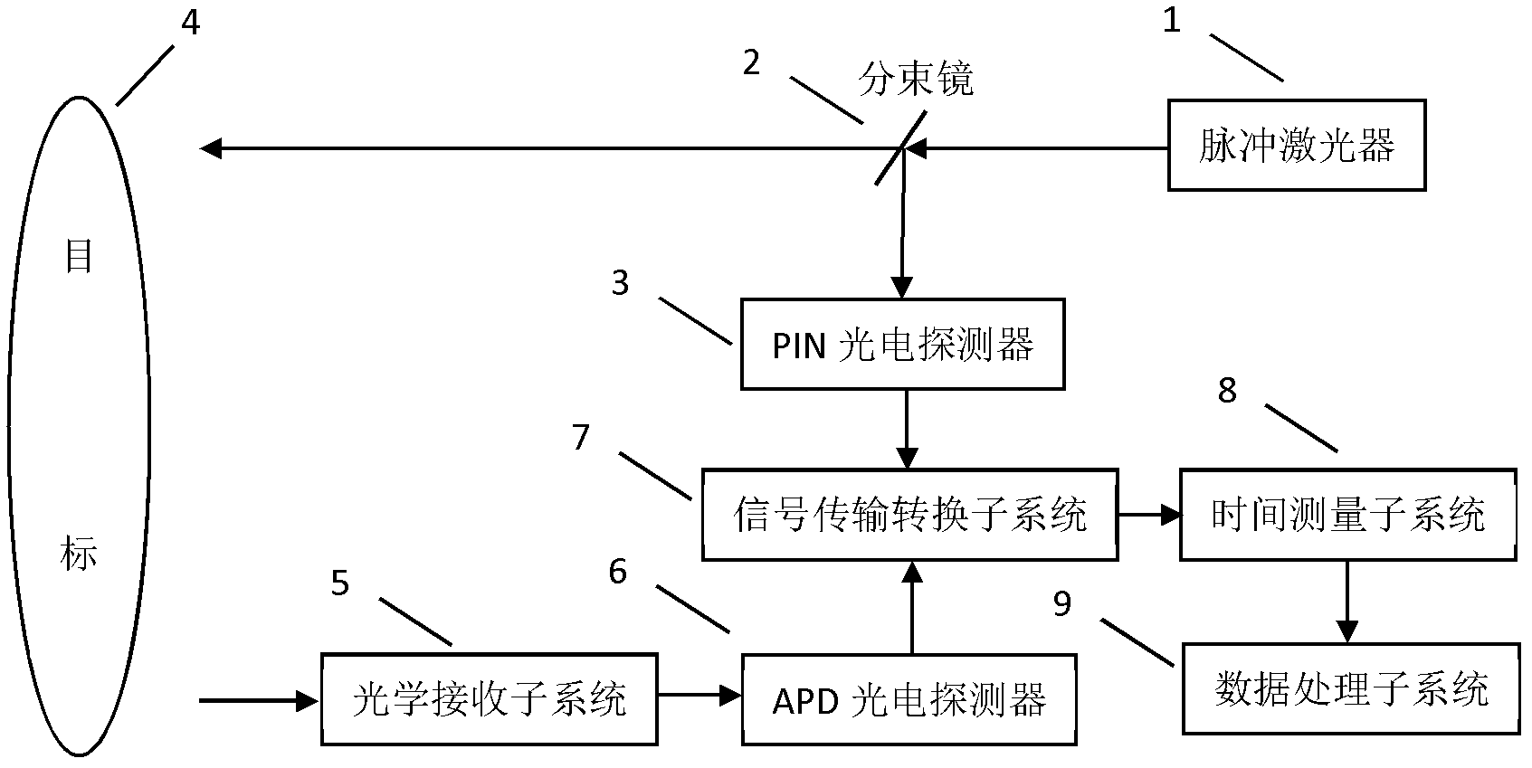
[0017] figure 1 The principle of pulse laser ranging is shown. The pulse laser 1 emits laser pulses, which are split by the beam splitter 2. Most of the laser energy is sent to the target 4, and a small amount of laser energy is received by the PIN photodetector 3. The laser pulse is irradiated on the surface of the target 4 to produce diffuse reflection, and the laser echo is converged to the APD photodetector 6 by the optical receiving subsystem 5 .

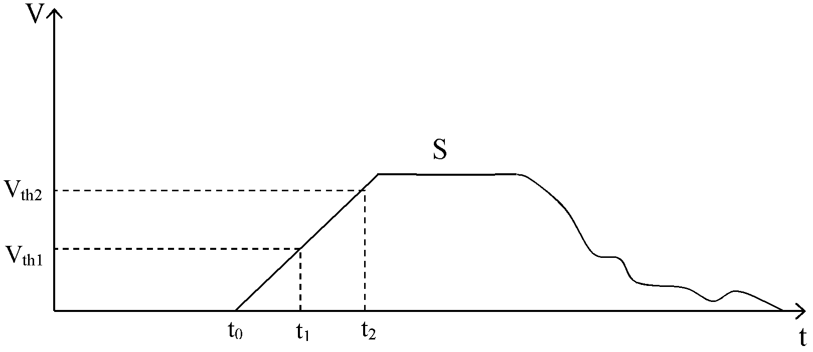
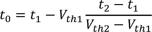
[0018] The signal transmission conversion subsystem 7 receives and processes the electrical signals output by the PIN photodetector 3 and the APD photodetector 6 . Since the amplitude and shape of the laser pulse emitted by the pulsed laser 1 are stable, the amplitude and shape of the electrical signal output by the PIN photodetector 3 are also stable, and the start timing signal obtained through a single fixed threshold has no time drift error. The electrical signal output by the APD photodetector 6 is triggered by the leadin...


PUM


Abstract

The invention discloses a pulse laser distance measuring method. A laser emission system, a laser echo receiving system and a data receiving and processing system are adopted for measurement, and the method is characterized in that the laser emission system comprises a pulse laser, a beam splitter and a PIN (personal identification number) photoelectric detector, the laser echo receiving system comprises an optical receiving subsystem, an APD (avalanche photo diode) photoelectric detector, the data receiving and processing system comprises a signal transmission converting subsystem, a time measuring subsystem and a data processing subsystem, the pulse laser is used for emitting laser pulses to be subjected to proportion beam splitting via the beam splitter, most of laser energy is emitted to a target, a small amount of the laser energy is received by the PIN photoelectric detector, the optical receiving subsystem is used for collecting laser echo onto the APD photoelectric detector, the signal transmission converting subsystem is used for receiving electric signals output by the PIN photoelectric detector and the APD photoelectric detector, the electric signals are transmitted to the time measuring subsystem after being subjected to signal processing, and the data processing subsystem is used for processing measurement data output by the time measuring subsystem and computing to obtain distance information of the target.

Description

technical field [0001] The invention relates to the field of pulse laser ranging, in particular to a method for identifying the time of laser echo. Background technique [0002] The basic principle of pulsed laser ranging is to actively emit laser pulses to the target, then detect the laser echo of the irradiated point on the target, measure the flight time of the laser pulse, and calculate the distance information of the target. Because the laser pulse is affected by the atmosphere and target scattering characteristics, the laser echo has great differences in amplitude and shape, and the resulting time drift error makes it difficult to accurately determine the laser echo time. At present, there are four main methods for laser echo time identification: frontier identification method, constant ratio identification method, high-pass capacitive resistance identification method and error compensation method. [0003] The leading edge discrimination method uses a single fixed th...

Claims


Application Information

Patent Timeline
Patent Type & Authority Applications(China)
IPC IPC(8): G01S17/08
Inventor 陈瑞强江月松谢拥军何云涛唐华
Owner BEIHANG UNIV
Why Eureka
Try Eureka