Anti-Reflection Optical Element and Method for Manufacturing Anti-Reflection Optical Element

An optical element and anti-reflection technology, which is applied in the direction of optical elements, optical elements, chemical instruments and methods, etc., can solve the problems of anti-reflection performance reduction, destruction of micro-concave-convex structures, etc., to suppress reflection and improve resistance to high temperature and high humidity environments , High-temperature and high-humidity environment resistance and excellent scratch resistance

Inactive Publication Date: 2012-09-19
TAMRON
View PDF5 Cites 7 Cited by
  • Summary
  • Abstract
  • Description
  • Claims
  • Application Information

AI Technical Summary

Problems solved by technology

Therefore, there is a problem that, for example, when stored for a long time in a high-temperature and high-humidity environment, moisture is adsorbed on the fine uneven structure and the fine uneven structure is destroyed, resulting in a decrease in antireflection performance.

Method used


Image

  • Anti-Reflection Optical Element and Method for Manufacturing Anti-Reflection Optical Element
  • Anti-Reflection Optical Element and Method for Manufacturing Anti-Reflection Optical Element
  • Anti-Reflection Optical Element and Method for Manufacturing Anti-Reflection Optical Element

Examples


Embodiment 1

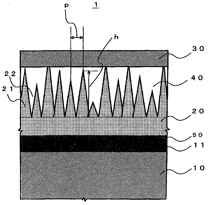
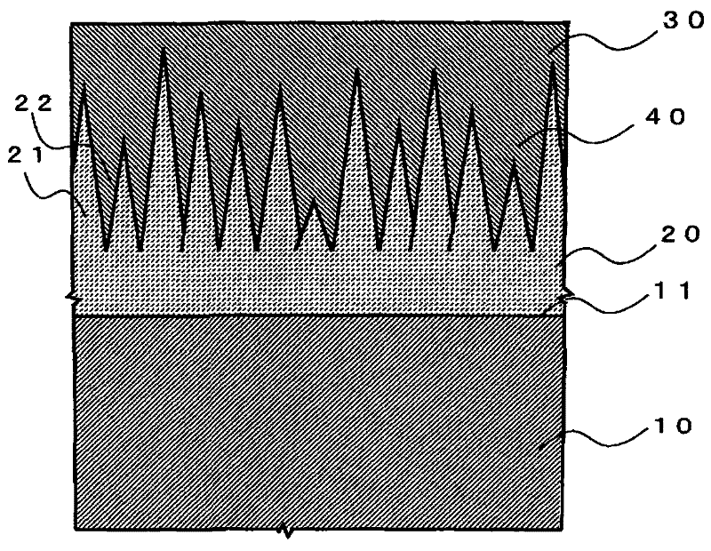
[0101] In Example 1, the optical element main body 10 made of glass is used, and the fine concave-convex structure 20 made of PMMA resin is formed on the optical surface 11 of the optical element main body 10, and it is used as an inorganic light-transmitting material thereafter. SiO 2 , and cover the outside of the fine concave-convex structure 20 with the covering layer 30 . Specifically, the antireflection optical element of Example 1 was manufactured in the following manner.

[0102] First, as the optical element main body 10 , a glass lens made of optical glass (trade name: S-LAH66 (nd=1.77)) manufactured by OHARA Corporation was used. In addition, for the PMMA resin film with a film thickness of 0.2 mm set on the optical surface 11 of this glass lens, use a vacuum evaporation device ARES1510 (Leybold Optics), on the surface of the PMMA resin film, by electron beam evaporation, form 1.25nm TiO measured on a quartz crystal microbalance 2 membrane. At this time, the eva...

Embodiment 2

[0104] In Example 2, a glass lens made of optical glass manufactured by OHARA Corporation (trade name: S-LAH55 (nd=1.83)) was used as the optical element main body 10 . Then, on the optical surface 11 of the optical element main body 10, after forming an optical film 50 composed of four layers (the first layer to the fourth layer) shown in Table 1 in the following order, on the optical film 50, a layer made of PMMA is formed. A fine uneven structure 20 made of resin. Thereafter, as an inorganic light-transmitting material, SiO 2 As a film-forming material, the outside of the fine concave-convex structure 20 was covered with the coating layer 30 in the following procedure. Specifically, the antireflection optical element of Example 2 was produced in the following manner.

[0105] First, on the glass lens made of S-LAH55 as the optical element main body 10, Al 2 o 3 film as the first layer. Then, on the surface of the first layer, ZrO 2 +TiO 2 membrane. In the same way a...

Embodiment 3

[0111] The film thickness of each layer of the optical thin film 50 provided between the optical surface 11 of the optical element main body 10 and the fine concave-convex structure 20 is shown in Table 2. material while using TiO 2 , and the film thickness of the cover layer 30 was set to 5 nm, all the same as the anti-reflection optical element produced in Example 2, and the anti-reflection optical element of Example 3 was produced.

[0112] Table 2

[0113]


PUM

PropertyMeasurementUnit
thicknessaaaaaaaaaa
thicknessaaaaaaaaaa
thicknessaaaaaaaaaa

Abstract

An object of the present invention is to provide an anti-reflection optical element excellent in durability in the environment high-temperature and high-humidity and scratch resistance while maintaining the anti-reflection performance of a concave-convex nanostructure. To achieve the object, an anti-reflection optical element 1 comprising a concave-convex nanostructure 20 that reduces reflection of incident light on an optical surface 11 of a base optical element 1 comprising a cover layer 30 made of a light-transmitting material that covers an outer surface of the concave-convex nanostructure 20, wherein a peak of convex portion 21 of the concave-convex nanostructure 20 is covered with the cover layer 30 in the state where a space 40 is provided between the cover layer 30 and concave portions 22 of the concave-convex nanostructure 20 is employed.

Description

technical field [0001] The present invention relates to an anti-reflection optical element having an anti-reflection structure on the optical surface of an optical element main body and a method for manufacturing the anti-reflection optical element, and particularly to an anti-reflection optical element having a fine concave-convex structure that suppresses reflection of incident light as an anti-reflection structure. A reflective optical element and a method for manufacturing the anti-reflective optical element. Background technique [0002] Conventionally, an antireflection optical element having an antireflection structure on an optical surface of an optical element such as a lens to reduce loss of transmitted light due to surface reflection has been used. As one of the antireflection structures, there is known a fine concavo-convex structure in which protrusions are regularly arranged at intervals shorter than the wavelength of incident light (for example, refer to "Pate...

Claims


Application Information

Patent Timeline
Patent Type & Authority Applications(China)
IPC IPC(8): G02B1/11B32B3/24B32B3/30B32B27/06G02B1/118G02B1/14
CPCB32B27/308B32B27/365G02B1/118G02B2207/101B32B27/325B32B3/30B32B2551/00B32B27/286B82Y20/00B32B27/281
Inventor 宫原正明国定照房涩谷穰
Owner TAMRON
Why Eureka
Try Eureka