Spatial filter and laser amplification device adopting same

A space filter and laser beam technology, applied in the field of optics, can solve the problems of self-excited oscillation, the transmittance of the window cannot reach 100%, and the damage is large. It is easy to realize, avoid laser self-excited oscillation, and easy to operate. Effect

Inactive Publication Date: 2012-09-19
BEIJING GK LASER TECH
View PDF5 Cites 2 Cited by
  • Summary
  • Abstract
  • Description
  • Claims
  • Application Information

AI Technical Summary

Problems solved by technology

[0003] In traditional spatial filters, windows are pressed by figure 1 In the placement shown, the window is perpendicular to the axis of the spatial filter. The disadvantage of this placement is that since the transmittance of the window cannot be 100%, there will always be some residual reflection when the incident laser beam travels along the axis of the spatial filter. When the axis propagates, the two windows of the spatial filter form a resonant cavity with the mirror behind the laser amplifier respectively, and the laser beam is reflected back and forth between the window of the spatial filter and the mirror behind the laser amplifier to generate self-excited oscillation
[0004] In a high-gain multi-pass laser amplification device, self-excited oscillation consumes a large number of inversion particles. When the laser passes through the laser medium again, the number of inversion particles in the laser medium will decrease and the gain will not be sufficient.
Due to the emergence of self-excited oscillation, there will be a large energy of unnecessary laser light in the laser amplifier device, which will cause devastating damage to the laser amplifier device and some optical devices of the system, and may make the entire laser amplifier device suffered devastating damage
Especially for high-gain multi-pass laser amplification systems, the damage caused by this phenomenon is greater, making the reliability of the laser amplification device lower

Method used


Image

  • Spatial filter and laser amplification device adopting same
  • Spatial filter and laser amplification device adopting same
  • Spatial filter and laser amplification device adopting same

Examples


Embodiment 1

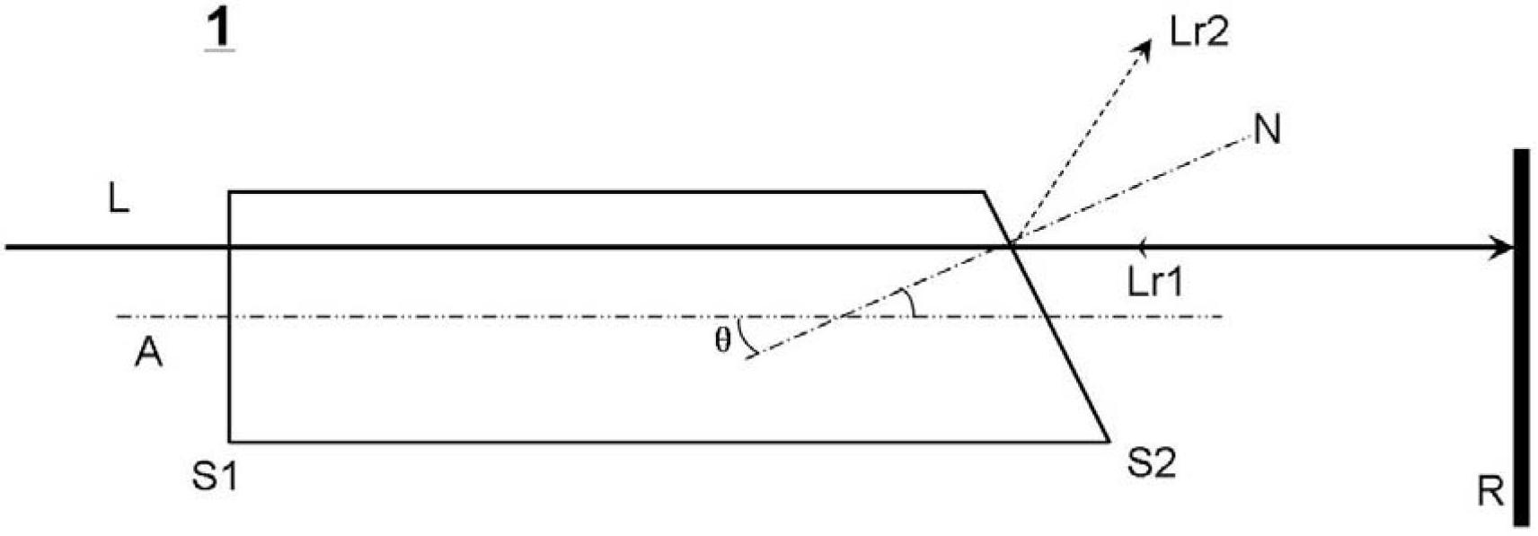
[0025] This embodiment provides a spatial filter 1, the structure of which is as follows figure 2 As shown, the spatial filter 1 is rod-shaped extending along the longitudinal axis A, which has windows S1 (incident window) and S2 (exit window), wherein the window S1 is perpendicular to the longitudinal axis A, that is, the window S1 The normal is parallel to the longitudinal axis A, and the window S2 is not perpendicular to the longitudinal axis A, that is, the normal N of the window S2 and the longitudinal axis A form an angle θ (0° figure 2 It is a schematic cross-sectional view obtained by cutting the spatial filter 1 along the plane where the normal N of the window S2 and the longitudinal axis A lie.

[0026] From figure 2 It can be seen that when the incident laser beam L enters the spatial filter perpendicular to the window S1, the incident laser beam L propagates along the direction of the longitudinal axis A and exits from the window S2, and finally enters the mirror...

Embodiment 2

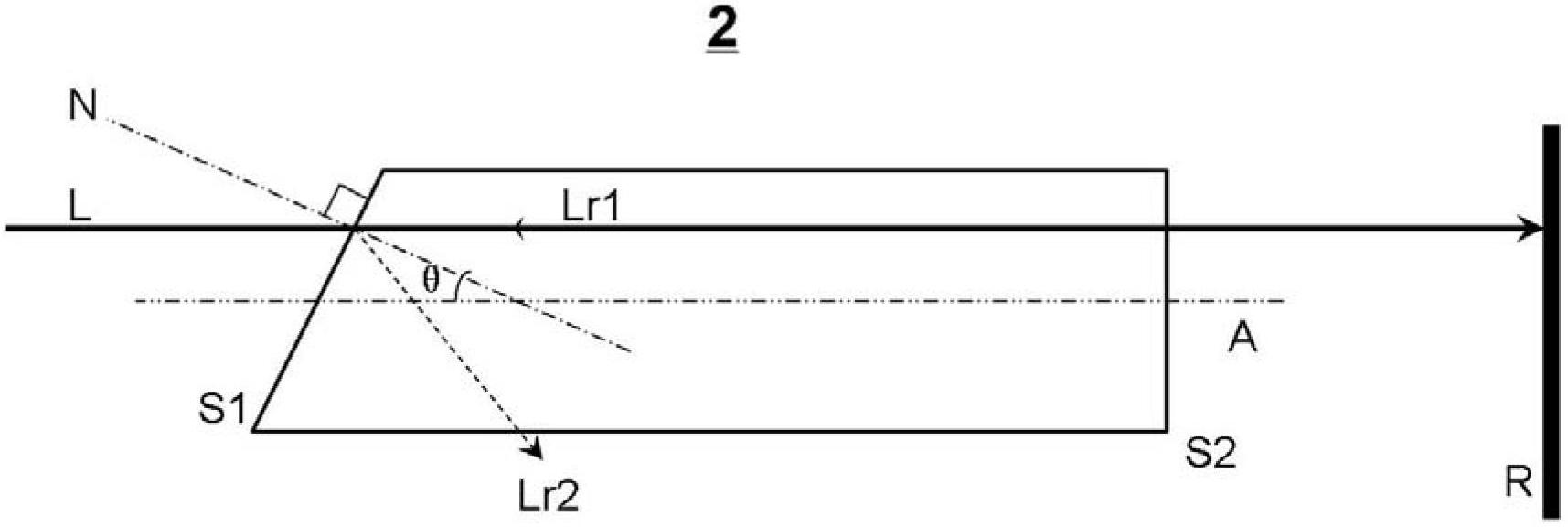
[0028] This embodiment provides a spatial filter 2, its structure is as follows image 3 As shown, the spatial filter 2 is rod-shaped extending along the longitudinal axis A, which has windows S1 (incident window) and S2 (exit window), wherein the window S2 is perpendicular to the longitudinal axis A, that is, the window S2 The normal line is parallel to the longitudinal axis A, and the window S1 is not perpendicular to the longitudinal axis A, that is, the normal N of the window S1 and the longitudinal axis A form an angle θ (0° image 3 It is a schematic cross-sectional view obtained by cutting the spatial filter 2 along the plane where the normal N of the window S1 and the longitudinal axis A lie.

[0029] From image 3 It can be seen that when the incident laser beam L is incident into the spatial filter parallel to the longitudinal axis A, the incident laser beam L propagates along the direction of the longitudinal axis A and exits from the window S2, and finally enters th...

Embodiment 3

[0031] This embodiment provides a spatial filter 3, its structure is as follows Figure 4 As shown, the spatial filter 3 is rod-shaped extending along the longitudinal axis A, and has windows S1 (incident window) and S2 (exit window), wherein both the windows S1 and S1 are non-perpendicular to the longitudinal axis A, and the window The normal N1 of the sheet S1 forms an included angle θ with the longitudinal axis A (0° Figure 4 It is a schematic cross-sectional view obtained by cutting the spatial filter 3 along the plane where the normal N1, the normal N2, and the longitudinal axis A are located.

[0032] From Figure 4 It can be seen that when the incident laser beam L is incident into the spatial filter parallel to the longitudinal axis A, the incident laser beam L propagates along the direction of the longitudinal axis A and exits from the window S2, and finally enters the mirror perpendicular to the longitudinal axis A On R, before it is incident on the mirror R, it als...


PUM


Abstract

The invention provides a spatial filter, which comprises a first window sheet and a second window sheet along a longitudinal axis, wherein a laser beam is incident into the first window sheet and transmitted from the second window sheet so as to get out of the spatial filter; and at least one of the first window sheet and the second window sheet is perpendicular to the longitudinal axis. The invention also provides a laser amplification device with the spatial filter.

Description

technical field [0001] The invention belongs to the field of optics, in particular to a spatial filter and a laser amplifying device using the spatial filter, especially a high-gain multi-pass laser amplifying device. Background technique [0002] For a multi-pass laser amplification device, it generally includes a spatial filter, a laser amplifier, and a mirror. figure 1 The middle is a schematic diagram of the optical path in the prior art laser amplification device. In the high-energy laser system, the spatial filter is one of the key technical units. Its optical structure is relatively simple, consisting of a pair of confocal positive lenses and a small aperture diaphragm at the common focus. The spatial filter is responsible for eliminating the high-frequency modulation in the laser beam, suppressing the small-scale self-focusing effect in the subsequent main amplifier, and performing image transfer on the beam. Image transfer through spatial filters reduces diffracti...

Claims


Application Information

Patent Timeline
Patent Type & Authority Applications(China)
IPC IPC(8): G02B27/46H01S3/00
Inventor 邱基斯樊仲维唐熊忻
Owner BEIJING GK LASER TECH
Why Eureka
Try Eureka