Modeling method for milling surface appearance of workpiece

A technology of workpiece surface and milling, which is applied in the direction of electrical program control, digital control, etc.

Inactive Publication Date: 2012-09-19
NANJING UNIV OF AERONAUTICS & ASTRONAUTICS
View PDF1 Cites 36 Cited by
  • Summary
  • Abstract
  • Description
  • Claims
  • Application Information

AI Technical Summary

Problems solved by technology

[0005] Most of the existing modeling methods of workpiece surface morphology are researches on the influence of factors such as cutting parameter selection, tool positioning error, and tool deformation caused by cutting force on the workpiece surface morphology. At present, there are few methods for ball-end milling Correlative research on the influence of tool dynamic wear on workpiece surface morphology during tool milling

Method used


Image

  • Modeling method for milling surface appearance of workpiece
  • Modeling method for milling surface appearance of workpiece
  • Modeling method for milling surface appearance of workpiece

Examples


Embodiment Construction

[0058] The technical solutions of the present invention will be described in detail below in conjunction with the accompanying drawings.

[0059] A method for modeling the surface topography of a milling workpiece, comprising the steps of:

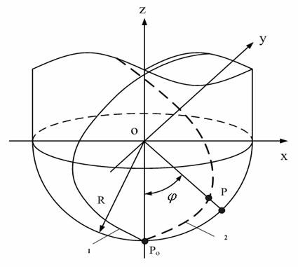
[0060] (1) The cutting edge of the ball-end milling cutter is discrete, and the micro-element milling trajectory equation of the cutting edge of the ball-end milling cutter is established.

[0061] According to the cutting motion trajectory of the milling tool, the cutting edge of the ball head is discretized into a series of cutting microelements, such as figure 1 Shown is the discrete schematic diagram of the cutting edge of the ball head in the present invention, the dotted line in the figure shows a helical cutting edge on the ball head part, P is a cutting element on it, O is the center of the ball head part, is the angle between the line connecting point P and the center O of the ball head and the tool spindle Z, which is the angle...


PUM


Abstract

The invention discloses a modeling method for milling the surface appearance of a workpiece, belonging to the field of digital milling. The modeling method comprises the steps of carrying out dispersing treatment on the cutting edge of a ball-end mill according to cutting movement locus of a milling cutter; establishing infinitesimal cutting locus equation of the cutting edge of the ball-end mill, wherein the surface appearance of the cutting locus equation is formed by the outermost side locus in the established locus equation; determining corresponding cutter turning angle range for milling the outermost side locus by judging the cutting infinitesimal position angle range corresponding to the outermost side locus; calculating corresponding milling time for milling the locus by combining with angular rotation speed obtained through a cutter spindle rotation speed; and obtaining the outermost side milling locus through a helical lag angle at the cutting infinitesimal position, thus obtaining the surface appearance of the milling workpiece. The modeling method can solve the generation problem on the surface appearance of the workpiece in milling process.

Description

[0001] technical field [0002] The invention belongs to the field of numerical control milling, in particular to the field of modeling the surface topography of workpieces caused by tool wear in numerical control milling. Background technique [0003] With the development of modern machinery manufacturing industry, the requirements for machining precision of parts are getting higher and higher. In the actual milling process, due to the influence of various factors, machining errors will inevitably occur. Machining error is a very important factor affecting the machining quality of workpieces, which will significantly reduce the machining accuracy of workpieces. Excessive machining errors will even cause parts to be scrapped, seriously affecting processing efficiency and benefits. The microscopic topography of the workpiece surface is closely related to the surface roughness of the workpiece, which has an important impact on the wear resistance and assembly accuracy of the ...

Claims


Application Information

Patent Timeline
Patent Type & Authority Applications(China)
IPC IPC(8): G05B19/19
Inventor 张臣郭松周来水张海艳
Owner NANJING UNIV OF AERONAUTICS & ASTRONAUTICS
Why Eureka
Try Eureka