

Inter-cell interference coordination method and system
A technology of inter-cell interference and coordination methods, applied in the field of communication, can solve problems such as inability to adapt to changes in network load, and achieve the effect of optimizing performance
- Summary
- Abstract
- Description
- Claims
- Application Information
AI Technical Summary
Problems solved by technology
Method used
Image

Examples
Embodiment 1
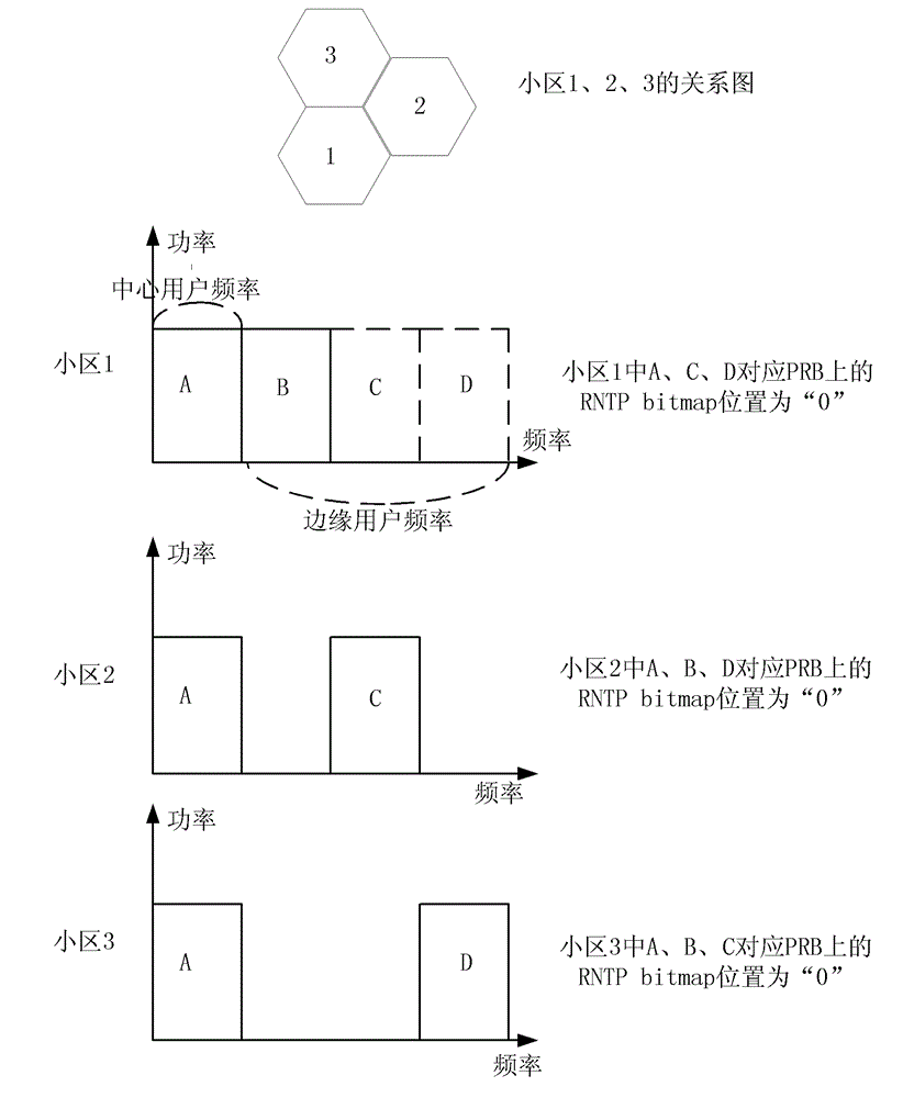
[0074] image 3 It is a schematic diagram of dividing frequency band resources and setting RNTP bitmap according to the preferred embodiment 1 of the present invention, such as image 3 As shown, it includes three cells that are adjacent to each other. The implementation of the technical solution will be further described in detail below with cell 1 as the main line.
[0075] It is assumed that TrdNum of the three cells is 3, and the initial RNTP Threshold is 1 dB.
[0076] (1) Divide frequency band resources.
[0077] The entire system bandwidth is divided into 4 parts, which are divided into PRB units, which can be continuous or discontinuous. The frequency band corresponding to frequency band A is the part that can be used by the centers of the three cells, and B is used by the edge of cell 1. C is used by the edge of cell 2, and D is used by the edge of cell 3;
[0078] (2) Set the RNTP bitmap.
[0079] The center of cell 1 can borrow the frequency bands C and D on the...
Embodiment 2
[0091] Figure 5 It is a schematic diagram of dividing frequency band resources and setting RNTP bitmap according to preferred embodiment 2 and preferred embodiment 3 of the present invention, such as Figure 5 As shown, it includes four cells with multi-layer neighbors, where the neighbors of cell 1 are cell 2 and cell 3 respectively, the neighbors of cell 2 are only cell 1, and the neighbors of cell 3 are cell 1 and cell 4 respectively, The only neighbor cell of cell 4 is cell 3.
[0092] It is assumed that TrdNum of all cells is 3, the initial RNTP Threshold of cells 1, 2, and 3 are all 1 dB, and the initial RNTP Threshold of cell 4 is 0 dB.
[0093] (1) Divide frequency band resources.
[0094] For attached Figure 5 In the shown cell, all frequency band resources are equally divided into 3 parts, where A is the dedicated frequency band for all center users of the cell, and for cell 1, the frequency band available to edge users is B; the available frequency band resourc...
Embodiment 3
[0106] by Figure 5 The cell shown is an example.
[0107] It is assumed that the initial RNTP Threshold of all cells 1, 2, 3, and 4 is 1dB. For details of the signaling process, see the attached Figure 7 .
[0108] (1) Divide frequency band resources.
[0109] For attached Figure 4 In the shown cell, all frequency band resources are equally divided into 3 parts, where A is the dedicated frequency band for all center users of the cell, and for cell 1, the frequency band available to edge users is B; the available frequency band resources for the edge of cells 2 and 3 are Region C; the frequency band resource available at the edge of cell 4 is region B.
[0110] (2) Set the RNTP bitmap.
[0111] The center of cell 1 can borrow the frequency band C at the edge of 2 and 3, so the part corresponding to B in the RNTP bitmap of cell 1 is set to "1", and the other frequency bands are set to "0"; similarly, the RNTP bitmaps of cells 2 and 3 correspond to The part of C is set ...
PUM
 Abstract
Description
Claims
Application Information