Main brake cylinder for a hydraulic vehicle brake system and method for operating same

A technology of master brake cylinder and vehicle braking, which is applied in the direction of hydraulic brake transmission device, brake action activation device, brake, etc., and can solve problems such as changes

Active Publication Date: 2012-09-19
ROBERT BOSCH GMBH
View PDF13 Cites 11 Cited by
  • Summary
  • Abstract
  • Description
  • Claims
  • Application Information

AI Technical Summary

Problems solved by technology

[0005] The difficulty in braking feedback is that the deceleration effect of the motor working as a generator depends on the situation and changes during braking

Method used


Image

  • Main brake cylinder for a hydraulic vehicle brake system and method for operating same
  • Main brake cylinder for a hydraulic vehicle brake system and method for operating same

Examples


Embodiment Construction

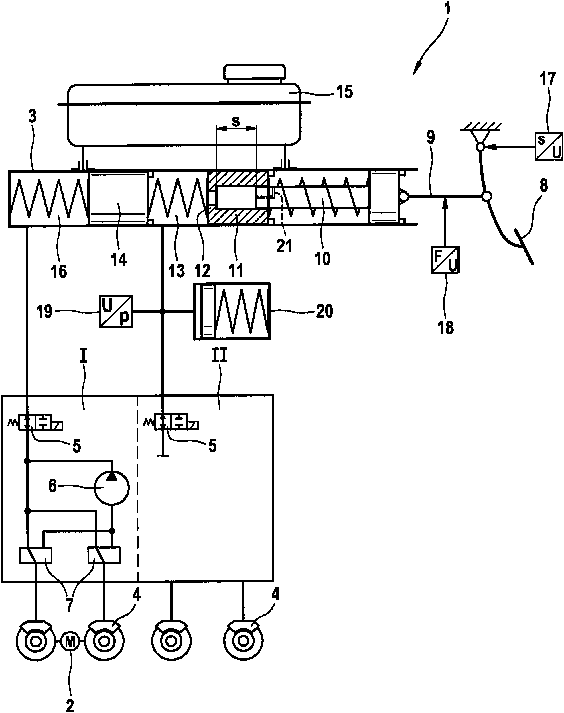
[0023] The hydraulic vehicle brake system 1 according to the invention shown in the drawing can be used in a hybrid vehicle (not shown), ie a vehicle having an internal combustion engine and an electric motor 2 as drive motors. The electric motor 2 acts on both wheels of the axle. It is also possible to use multiple electric motors for each wheel or for all wheels (not shown). The vehicle can also be a pure electric vehicle powered by the electric motor 2 without an internal combustion engine. During the braking process, the electric motor 2 (usually also referred to as the electric motor 2, and this name will be used hereinafter) works as a generator to generate current, which is stored in the battery not shown in the figure and can be used by the electric motor 2 to Drive the vehicle.

[0024] The vehicle braking system 1 is a dual-circuit vehicle braking system 1 having two braking circuits I, II connected to a tandem master brake cylinder 3 . The hydraulic wheel brakes ...


PUM


Abstract

The invention relates to a main brake cylinder (3) for a hydraulic vehicle brake system (1) of a motor vehicle, which comprises an electric motor (2) that is operated as a generator for decelerating the motor vehicle. For service braking, pressure is applied to a brake circuit Il by the main brake cylinder (3) and to another brake circuit I by a hydraulic pump (6). In order to reduce a pedal force, according to the invention a first piston (10) has a smaller piston surface and a second piston (11) only moves if a greater brake fluid volume is required. A preloaded hydraulic accumulator (20) limits an increase in pressure.

Description

technical field [0001] The invention relates to a master brake cylinder for a vehicle hydraulic brake system having the features stated in the preamble of claim 1 and to a method of operating a master brake cylinder having the features stated in the preamble of claim 5 . Background technique [0002] As is well known, hybrid vehicles have an internal combustion engine and one (or more) electric motors used to drive the vehicle. In order to decelerate such a motor vehicle, the electric motor can be operated as a generator and the resulting electrical current is stored in a battery. The use of an electric motor acting as a generator to slow down a motor vehicle is called regenerative braking. An electric motor is generally to be understood as an electrical machine, which can also be a generator, for example. [0003] In order to achieve a defined deceleration, the braking effect of the vehicle's hydraulic braking system must be reduced by as much as the decelerating effect o...

Claims


Application Information

Patent Timeline
Patent Type & Authority Applications(China)
IPC IPC(8): B60T7/02B60T8/00B60T11/10B60T11/16
CPCB60T7/042B60T13/165B60T7/02B60T11/10B60T8/00B60T8/38B60T11/16B60T8/4081
Inventor M・孔茨
Owner ROBERT BOSCH GMBH
Why Eureka
Try Eureka