
Electrically-controlled fuel injector for large diesel engines

A technology for diesel engines and fuel injectors, which is applied to fuel injection devices, special fuel injection devices, engine components, etc., to achieve the effect of minimizing required emissions and optimizing performance

Active Publication Date: 2012-09-26
OMT OFF MEC TORINO
View PDF4 Cites 9 Cited by
  • Summary
  • Abstract
  • Description
  • Claims
  • Application Information

AI Technical Summary

Problems solved by technology

[0014] These issues make it difficult to implement mature common rail technology into injectors for large two-stroke engines

Method used


Image

  • Electrically-controlled fuel injector for large diesel engines
  • Electrically-controlled fuel injector for large diesel engines
  • Electrically-controlled fuel injector for large diesel engines

Examples


Embodiment Construction

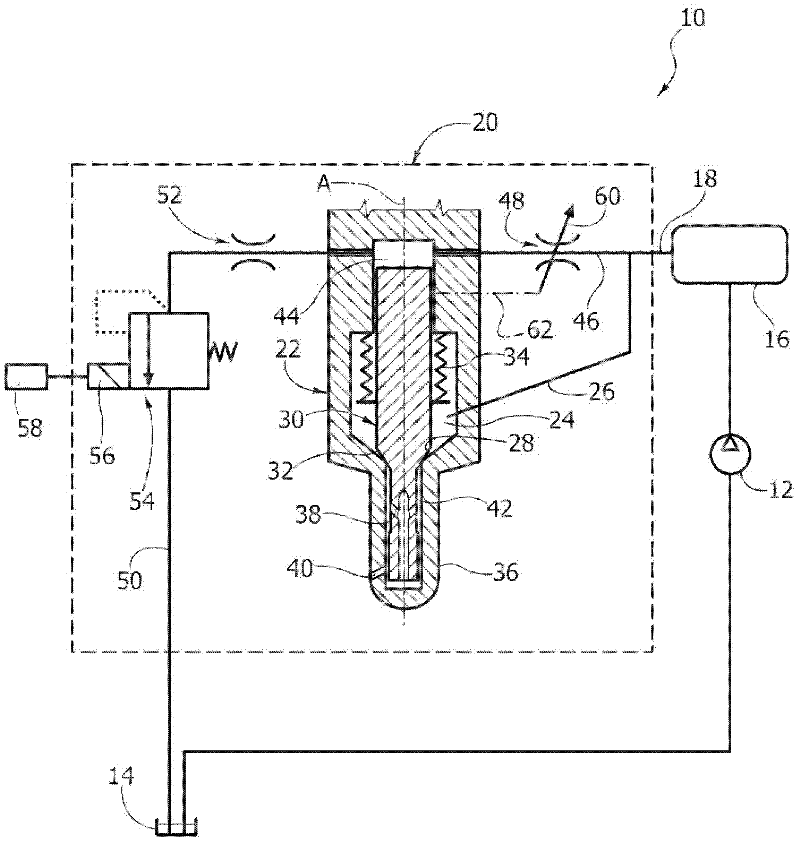
[0028] see figure 1 , an injection system for a diesel engine is indicated by reference numeral 10 . The injection system includes a charge pump 12 that draws fuel from a low pressure fuel storage tank 14 and delivers the pressurized fuel to a high pressure common rail 16 . The common rail 16 is connected to a plurality of high-pressure pipelines 18 (in figure 1 Only one is shown in ), each delivery high pressure line is connected to a respective injector 20.

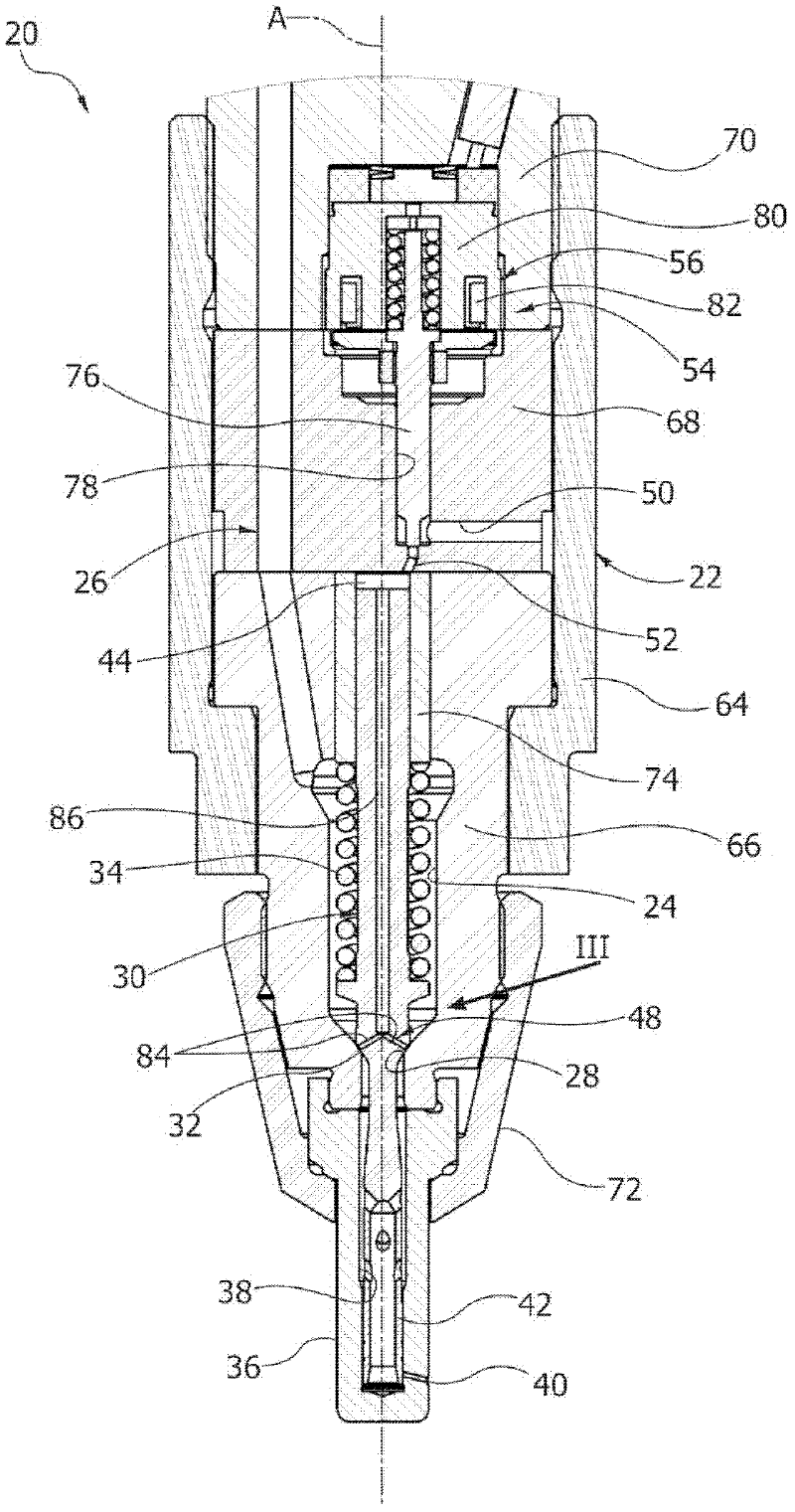
[0029] Injector 20 includes a body 22 having a delivery chamber 24 connected to high pressure line 18 by a fuel supply line 26 . The delivery chamber 24 has a conical valve seat 28 .

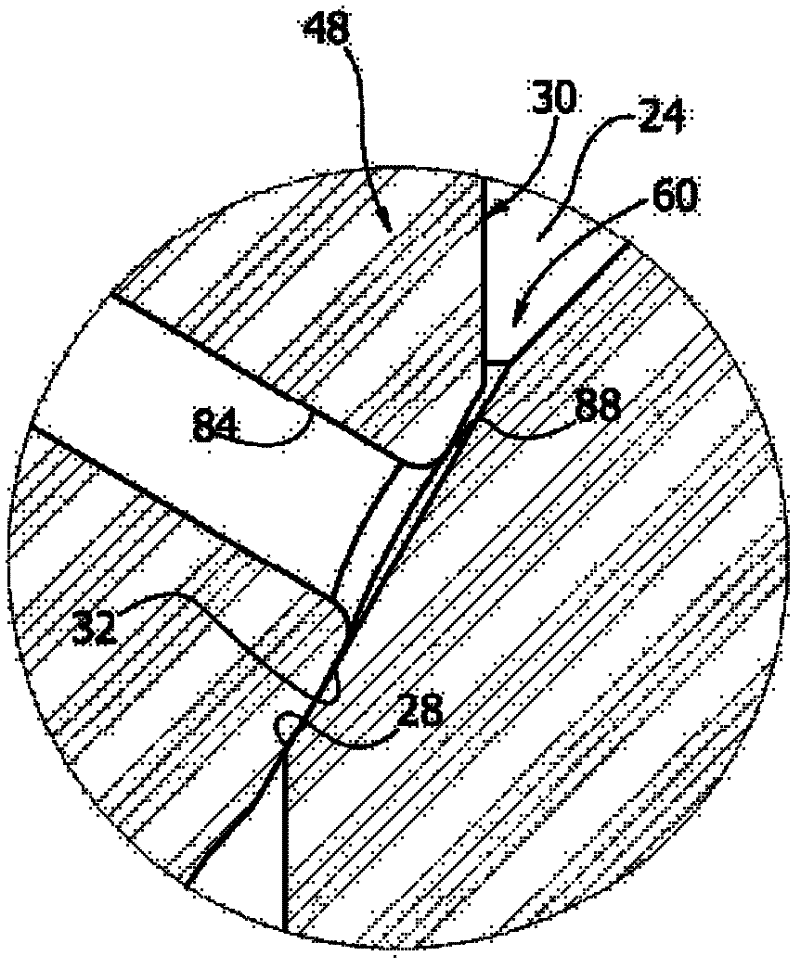
[0030] The injector 20 includes a valve needle 30 that extends through the delivery chamber 24 and has a conical sealing surface 32 that cooperates with the valve seat 28 . Valve needle 30 is movable along longitudinal axis A between a closed position and an open position. In the closed position, the sealing surface 32 abuts the valv...


PUM


Abstract

An electrically controlled fuel injector for large diesel engines, comprising: - a body having a delivery chamber connected to a fuel supply line and provided with a conical valve seat; - a needle extending through said delivery chamber and having a conical sealing surface cooperating with said valve seat, the needle being movable along a longitudinal axis between a closed position wherein said conical sealing surface abuts against said conical valve seat and an open position wherein said conical sealing surface is spaced apart from said conical valve seat, wherein the hydraulic pressure into said delivery chamber generates a first hydraulic force pushing the needle towards its open position; - a control chamber connected to said fuel supply line through an inlet flow restrictor and connected to a discharge line through an outlet flow restrictor, wherein the hydraulic pressure into said control chamber generates a second hydraulic force pushing the needle towards its closed position; - an electrically-operated control valve for selectively opening and closing hydraulic communication between said control chamber and a low pressure volume; wherein said inlet flow restrictor includes a variable choking section, movable between a choked position corresponding to a fully closed position of the needle an un-choked position corresponding to an initial opening of the needle.

Description

technical field [0001] This invention relates to electronically controlled fuel injectors for large diesel engines. The invention particularly relates to fuel injectors for common rail injection systems of large two-stroke diesel engines, such as marine propulsion diesel engines. Background technique [0002] A common rail high pressure injection system consists of a pump that supplies fuel to the injectors, usually with a fixed displacement, and designed to pressurize the fuel in a high pressure accumulator (common rail). The injector is equipped with a valve seat, and a valve needle movable within the body of the injector between a closed position and an open position. The position of the valve needle is determined by the strength of the two hydraulic forces produced by the action of the pressurized liquid on the appropriate influencing surface. [0003] The pressurized fuel in the delivery chamber upstream of the valve seat acts in the direction in which the valve needl...

Claims


Application Information

Patent Timeline
IPC IPC(8): F02M51/06F02M47/02F02M61/06
CPCF02M2200/28F02M47/027F02M61/10F02M61/042
Inventor 马可·科波克劳迪奥·内格里
Owner OMT OFF MEC TORINO
Learn More