
Power amplifier

An amplifier and MOS tube technology, applied in amplifiers, improved amplifiers to reduce noise effects, amplifiers with semiconductor devices/discharge tubes, etc., can solve the problem that power amplifiers cannot effectively suppress power supply noise, save design space, improve PSRR, the effect of improving integration

Active Publication Date: 2015-02-04
SHANGHAI AWINIC TECH CO LTD
View PDF5 Cites 0 Cited by
  • Summary
  • Abstract
  • Description
  • Claims
  • Application Information

AI Technical Summary

Problems solved by technology

[0004] The technical solution of the present invention solves the problem that existing power amplifiers cannot effectively suppress power supply noise

Method used


Image

  • Power amplifier
  • Power amplifier
  • Power amplifier

Examples


Embodiment Construction

[0037] The specific embodiments of the present invention will be described in detail below in conjunction with the accompanying drawings. In the following paragraphs the invention is described more specifically by way of example with reference to the accompanying drawings. The advantages and features of the present invention will become clearer from the following description.

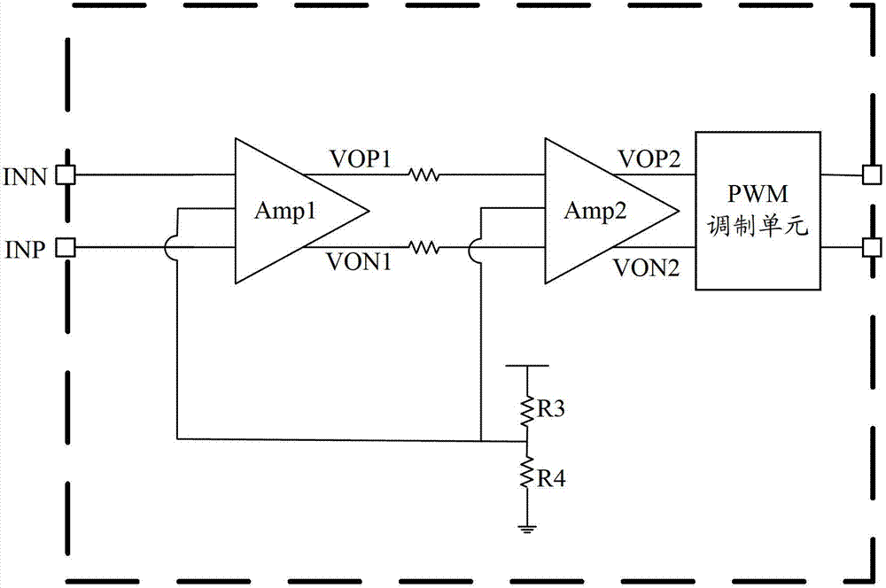
[0038] A major source of noise in Class D amplifiers is the power supply itself. Such as figure 1 As shown, the existing class D power amplifier chip has a first amplifier Amp1, a second amplifier Amp2 and a PWM modulation unit connected in sequence. The first amplifier Amp1 has a first input terminal INN, a second input terminal INP, a first output terminal VOP1 and a second output terminal VON1. The first output terminal VOP1 and the second output terminal VON1 of the first amplifier Amp1 are respectively connected to two input terminals of the second amplifier Amp2. The first output terminal VOP2...


PUM


Abstract

The technical scheme of the invention provides a power amplifier which comprises a bandgap reference circuit and a first amplifier, wherein the bandgap reference circuit is suitable for generating a first common-mode voltage and is connected with the common-mode voltage input terminal of the first amplifier so as to provide the common-mode voltage to the first amplifier; and the bandgap reference circuit is also suitable for generating a first reference current and is connected with the reference current input terminal of the first amplifier so as to offer reference current to the first amplifier. According to the technical scheme adopted by the invention, the bandgap reference circuit offers not only the reference current, but also the common mode voltage to the first amplifier, and as a result, the PSRR (Power Supply Rejection Ratio) of the whole power amplifier is improved. Moreover, the power amplifier has the advantages of simple structure and low alteration cost.

Description

technical field [0001] The invention relates to the field of amplifiers, in particular to a power amplifier. Background technique [0002] The Chinese patent application with the publication number CN 101958690A discloses a class D audio power amplifier circuit. The two input ends of the first stage amplifier are connected to audio signals, and the two output ends of the first stage amplifier are connected in series with input resistors and then connected to the second stage amplifier. The two input ends of the two feedback resistors are connected to the two pairs of input and output ends of the first-stage amplifier; one output end of the second-stage amplifier is connected in series with the first comparator, and the first drive circuit is connected to an input end of the speaker. The other output end of the second-stage amplifier is connected in series with the second comparator, the second drive circuit is connected to the other input end of the speaker, two feedback cap...

Claims


Application Information

Patent Timeline
Patent Type & Authority Patents(China)
IPC IPC(8): H03F3/217H03F1/26
Inventor 管少钧张振浩杜黎明李俊杰万幸
Owner SHANGHAI AWINIC TECH CO LTD
Learn More