Fluid-cooling device for a turbine engine propulsive unit

A technology of turbine engine and cooling device, which is applied in the direction of engine cooling, turbine/propulsion device cooling, engine components, etc., and can solve problems such as reduced propeller efficiency

Inactive Publication Date: 2012-09-26
AIRBUS OPERATIONS GMBH
View PDF5 Cites 7 Cited by
  • Summary
  • Abstract
  • Description
  • Claims
  • Application Information

AI Technical Summary

Problems solved by technology

[0011] -Dynamic air flow outside the nacelle is distorted resulting in reduced propeller efficiency

Method used


Image

  • Fluid-cooling device for a turbine engine propulsive unit
  • Fluid-cooling device for a turbine engine propulsive unit
  • Fluid-cooling device for a turbine engine propulsive unit

Examples


Embodiment Construction

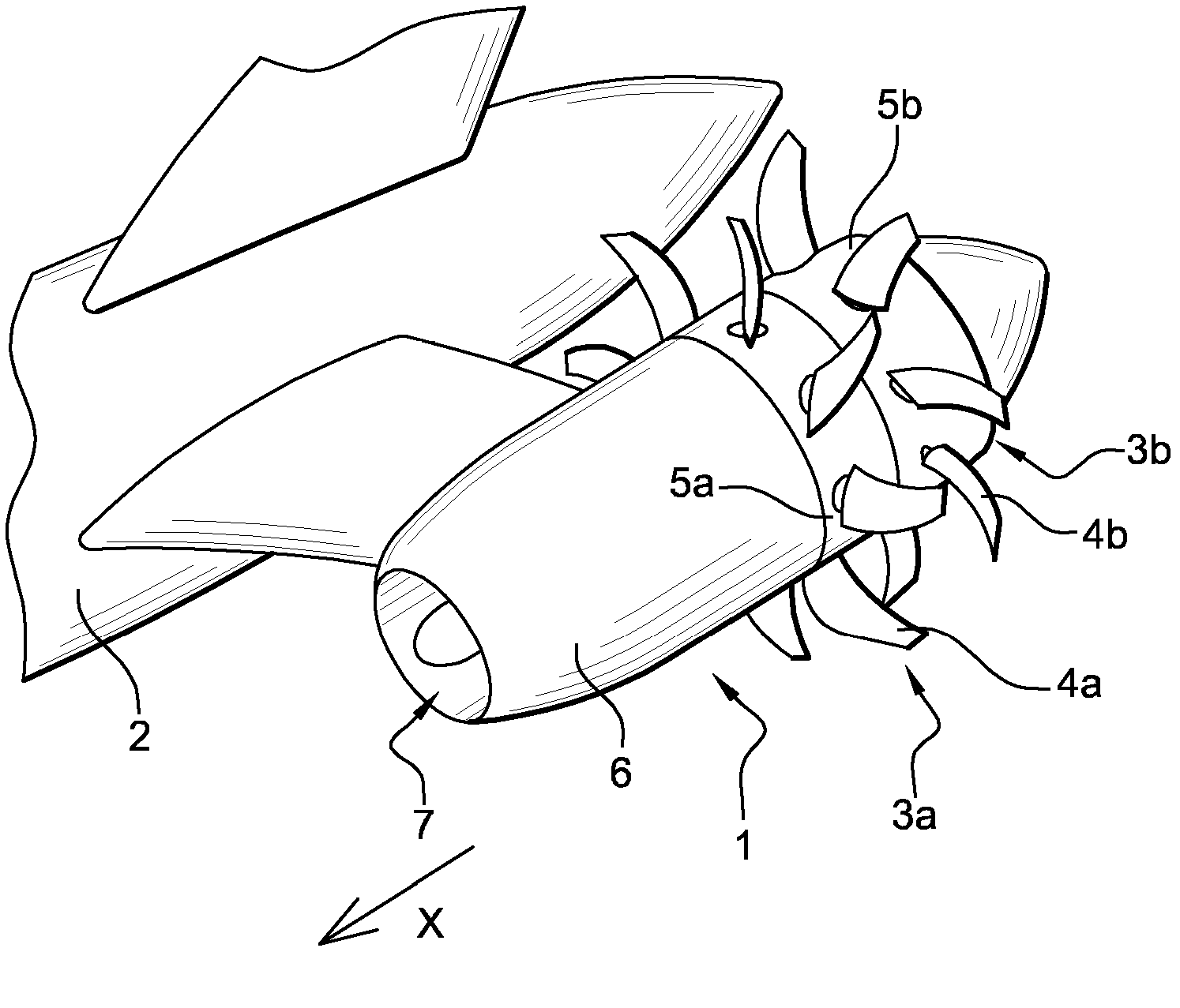
[0046] The present invention is mainly used in propeller 1 of aircraft, as attached figure 1 A propfan aircraft propeller, shown in , is designed to be used on future aircraft. In this embodiment, two propellers 1 are fixed on both sides of the rear of the fuselage 2 of the aircraft by hangers.

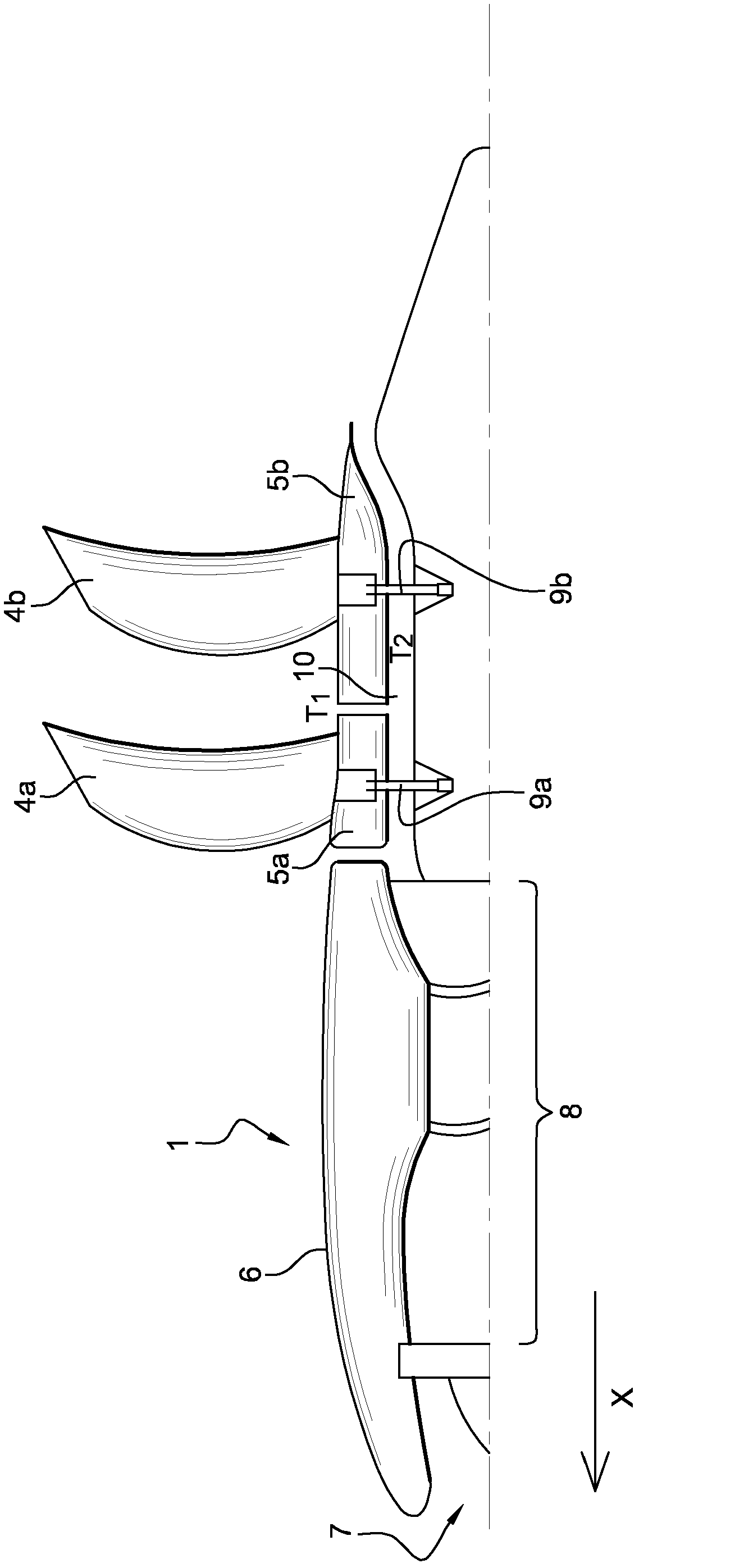
[0047] Here, each propeller 1 includes two counter-rotating rotors 3a, 3b, each rotor includes a set of equidistant blades 4a, 4b, and is arranged at the rear of the propeller 1, each rotor The blades 4a, 4b of 3a, 3b protrude from annular crowns 5a, 5b which move together with the rotor, the outer surface of which rests on the continuation of the casing 6 of the propeller.

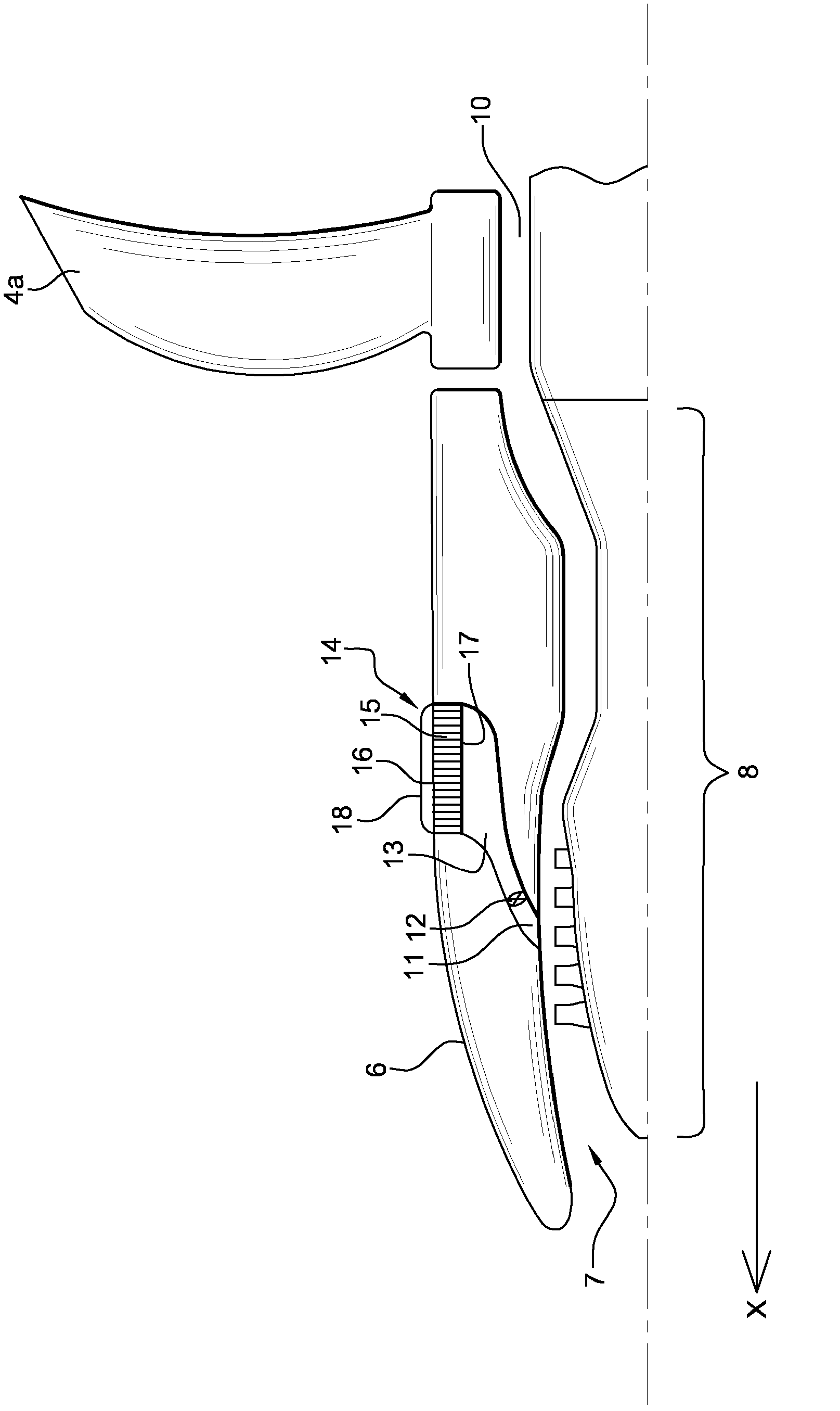
[0048] as attached figure 2 As shown, the propeller 1 comprises an air inlet 7 for supplying air to a turbine engine 8 comprising an axial portion which is driven in rotation when the turbine engine is in operation, said shaft passing through figure 2 A mechanical transmission, not shown, drives the shafts 9...


PUM


Abstract

The invention relates to a fluid cooling device (1) for the propulsive unit of an aircraft of the so-called propfan type, comprising a compressed air intake (11) at the air compressor of the turbine engine (8), an air seam (13) capable of conveying the collected compressed air to a cooler (14), means for conveying the heat of the lubricant to the cooler, said cooler (14) comprising a matrix body (15) provided with a plurality of pipes (20) for a coolant, said pipes (20) extending along a first so-called inner surface (17) up to a second so-called outer surface (16) of the matrix body (15), such that the collected compressed air serving as a coolant can pass through the matrix body (15), the matrix body (15) of the cooler (14) forming a portion of the outer skin (6) of the propulsive unit, as well as a blade assembly (18) extending from the outer surface (16); towards the outside of the propulsive unit, and oriented mainly parallel to the air flow direction (X) when the aircraft is in flight.

Description

technical field [0001] The invention relates to the field of aeronautical equipment, in particular heat dissipation systems, more particularly heat dissipaters for aircraft propellers with turbine engines. [0002] A number of aircraft propellers include turbine engines, such as propfan propellers, which drive two counter-rotating rotors. [0003] In said propeller, a gearbox (transmission between the turbine engine shaft and the rotor) transmits the mechanical energy generated by the turbine engine to the rotor. [0004] Although highly efficient, the gearbox converts a part of the energy generated by the propeller through friction into heat, which is transferred specifically to the lubricant in the gearbox. [0005] In addition, the turbine engine itself produces a large amount of heat dissipation, mainly by mechanical friction, through the lubricant. Background technique [0006] This heat should be dissipated to the external environment in order to cool the propfan. ...

Claims


Application Information

Patent Timeline
Patent Type & Authority Applications(China)
IPC IPC(8): F02C7/14F02C7/18F02K3/072
CPCF02K1/46B64D2033/0286F28D1/03F28F1/32F05B2260/2241B64D29/00F28F13/00F28D2021/0078B64D2027/026Y02T50/67F02C6/08F28D1/04F28F27/02Y02T50/672Y02T50/675F05D2220/325F28F1/34F04D29/584B64D2241/00F05B2220/305F02C7/14F02K3/072B64D33/10F28F2265/00Y02T50/60
Inventor 吉约姆·比兰拉尔夫-亨宁·施托尔特
Owner AIRBUS OPERATIONS GMBH
Why Eureka
Try Eureka