
Method and system for preventing catalyst blockage

A technology of catalyst and ash filter net, which is applied in the field of selective catalytic reduction reactor protection, can solve the problems of catalyst pore blockage, complex vibrating hammer mechanism, high wind speed of filter screen flow, etc., and achieve the effect of continuous operation, safe and efficient operation

Active Publication Date: 2012-10-03
CHINA HUADIAN ENG +1
View PDF5 Cites 11 Cited by
  • Summary
  • Abstract
  • Description
  • Claims
  • Application Information

AI Technical Summary

Problems solved by technology

For flue gas denitrification in coal-fired power plants, the catalyst must operate in a high-ash environment. The catalyst is generally installed in a vertical flue, and the flue gas passes through the pores of the catalyst vertically downward. The finer ash will flow through the pores of the catalyst, and the smaller Large ash cannot pass through the catalyst pores, which makes the catalyst pores blocked
The consequences of catalyst pore blockage are firstly that the activity of the catalyst is reduced, and the blocked catalyst surface cannot contact with the flue gas and loses the reaction ability; secondly, after the catalyst pore is blocked, the pressure loss will increase, and the flow rate of the unblocked catalytic pore will increase sharply , long-term operation leads to catalyst wear failure or even collapse, which seriously affects the safe and stable operation of the unit
[0003] Common catalyst soot blowing methods are steam or sonic wave. These soot blowing methods are mainly aimed at the dust adhering to the surface of the catalyst, but cannot solve the problem of catalyst pore blockage
Generally, catalyst manufacturers will add a layer of grille above the catalyst to prevent larger particles of ash from clogging the catalyst. However, the result is that the grille will be blocked by large ash particles and cannot be removed online, thus increasing The pressure drop of the entire system brings higher energy consumption, and long-term operation will also lead to catalyst wear, failure or even collapse, seriously affecting the safe and stable operation of the unit
[0004] The interception of dust particles with a particle size of more than 4 cm through the filter screen can be found in Chinese invention patents CN101227406B and CN101517318A, but these filters and their cleaning technologies have the following disadvantages: the filter screen has a high flow velocity, and it is easy to be eroded and damaged under high dust conditions. The rapping device directly contacts the filter screen, which is easy to cause damage to the filter screen, and the mechanism of the vibration hammer is complicated, which is not conducive to daily maintenance and high cost

Method used


Image

  • Method and system for preventing catalyst blockage
  • Method and system for preventing catalyst blockage
  • Method and system for preventing catalyst blockage

Examples


Embodiment 1

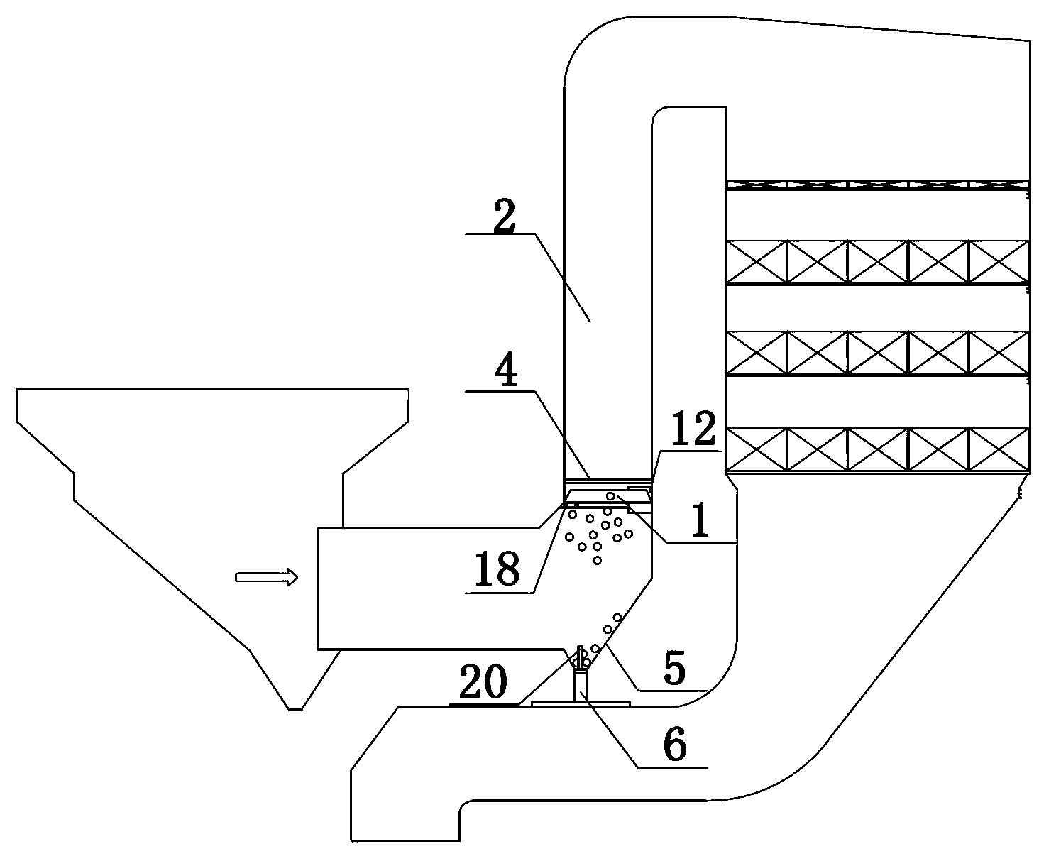
[0026] Embodiment 1 of the present invention: as figure 1 As shown, a system for preventing catalyst clogging includes a longitudinal flue 2 and a transverse flue 3. The longitudinal flue 2 is provided with an A dust filter 1, and only one end of the A dust filter 1 is movably connected with the longitudinal flue 2. , A zipper rapping device 4 is connected to the top of A dust filter net 1, A ash hopper 5 is arranged under A ash filter net 1, A ash hopper level meter 20 is arranged in A ash hopper 5, and the lower end of A ash hopper 5 is connected to A The discharge device 6 is connected. Since there is a dust filter net in the longitudinal flue, a zipper rapping device is arranged above the dust filter net, and an ash hopper is provided under the ash filter net, and the ash hopper is connected to the discharge device, which can not only prevent dust with a particle size of 4 cm or more The particles enter the catalyst layer, and the clogged dust on the ash filter can be dis...

Embodiment 2

[0036] Embodiment 2 of the present invention: as figure 1 As shown, a system for preventing catalyst clogging includes a longitudinal flue 2 and a transverse flue 3. The longitudinal flue 2 is provided with an A dust filter 1, and only one end of the A dust filter 1 is movably connected with the longitudinal flue 2. , A zipper rapping device 4 is connected to the top of A ash filter net 1, A zipper rapping device 4 is connected to A ash filter net 1, A ash hopper 5 is arranged under A ash filter net 1, A ash hopper 5 is provided with A The ash hopper level gauge 20, the lower end of the A ash hopper 5 is connected with the A discharge device 6. Since there is a dust filter net in the longitudinal flue, a zipper rapping device is arranged above the dust filter net, and an ash hopper is provided under the ash filter net, and the ash hopper is connected to the discharge device, which can not only prevent dust with a particle size of 4 cm or more The particles enter the catalyst ...

Embodiment 3

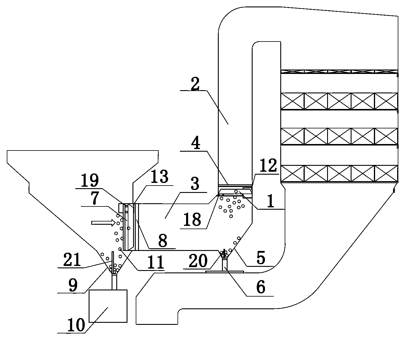
[0046] Embodiment 3 of the present invention: as figure 2 As shown, a system for preventing catalyst clogging includes a longitudinal flue 2 and a transverse flue 3. The longitudinal flue 2 is provided with an A dust filter 1, and only one end of the A dust filter 1 is movably connected with the longitudinal flue 2. , A zipper rapping device 4 is connected to the top of A ash filter net 1, A zipper rapping device 4 is connected to A ash filter net 1, A ash hopper 5 is arranged under A ash filter net 1, A ash hopper 5 is provided with A The ash hopper material level gauge 20, the lower end of the ash hopper 5 of A is connected with the discharge device 6 of A; the ash filter net 7 of B is arranged in the transverse flue 3, and only one end of the ash filter net 7 of B is flexibly connected with the transverse flue 3; One side of the ash net 7 is connected to the B zipper rapping device 8, the B zipper rapping device 8 is connected to the B ash filter net 7, and the B ash hoppe...


PUM


Abstract

The invention discloses a system for preventing catalyst blockage. The system comprises a longitudinal flue (2) and a transverse flue (3), wherein a dust gauze A (1) is arranged in the longitudinal flue (2); only one end of the dust gauze A (1) is movably connected with the longitudinal flue (2); a slide fastener rapping device A (4) is connected above the dust gauze A (1), and is connected with the dust gauze A (1); a dust hopper A (5) is arranged below the dust gauze A (1); an ash hopper lever meter (20) is arranged in the dust hopper A (5); and the lower end of the dust hopper A (5) is connected with a discharging device A (6). According to the system, dust particles of which the particle diameters are over 4 centimeters can be prevented from entering a catalyst layer, dust particles on the dust gauze can be discharged automatically under the condition of no stop of a boiler, and the system can run safely, efficiently and continuously at low pressure loss.

Description

technical field [0001] The invention relates to a selective catalytic reduction reactor protection method and device, in particular to a method and system for preventing catalyst blockage. Background technique [0002] During my country's "Twelfth Five-Year Plan" period, nitrogen oxide emissions were included in the binding index system for the first time, requiring a 10% reduction on the basis of 2010. Nitrogen oxides have become the focus of my country's "Twelfth Five-Year Plan" pollutant emission reduction. my country has promulgated the most stringent NOx emission standards in the world. Most coal-fired power plant boilers need to add denitrification devices. Due to the strict NOx emission standards in my country, most denitrification devices use the SCR method for denitrification. The principle of the SCR method is in the catalyst. If there is, NOx is reduced to N2 by spraying the denitration reducing agent ammonia into the reactor. The reaction temperature of this proc...

Claims


Application Information

Patent Timeline
IPC IPC(8): B01D53/86B01D53/56B01D46/12
Inventor 汪洋胡永锋陶爱平沈煜晖张国新李建浏
Owner CHINA HUADIAN ENG
Learn More