Mechanical hand control system

A control system and manipulator technology, applied in the direction of manipulators, manufacturing tools, chucks, etc., can solve the problem of no independent control device

Inactive Publication Date: 2012-10-03
TIANJIN POLYTECHNIC UNIV
View PDF0 Cites 6 Cited by
  • Summary
  • Abstract
  • Description
  • Claims
  • Application Information

AI Technical Summary

Problems solved by technology

[0005] Manipulators are usually used as additional devices for machine tools or other machines, such as loading, unloading and transferring workpieces on automatic machine tools or automatic production lines, changing tools in machining centers, etc., generally without independent control devices

Method used


Image

  • Mechanical hand control system
  • Mechanical hand control system
  • Mechanical hand control system

Examples


Embodiment Construction

[0035] A manipulator control system of the present invention will be described in detail below in conjunction with embodiments and drawings.

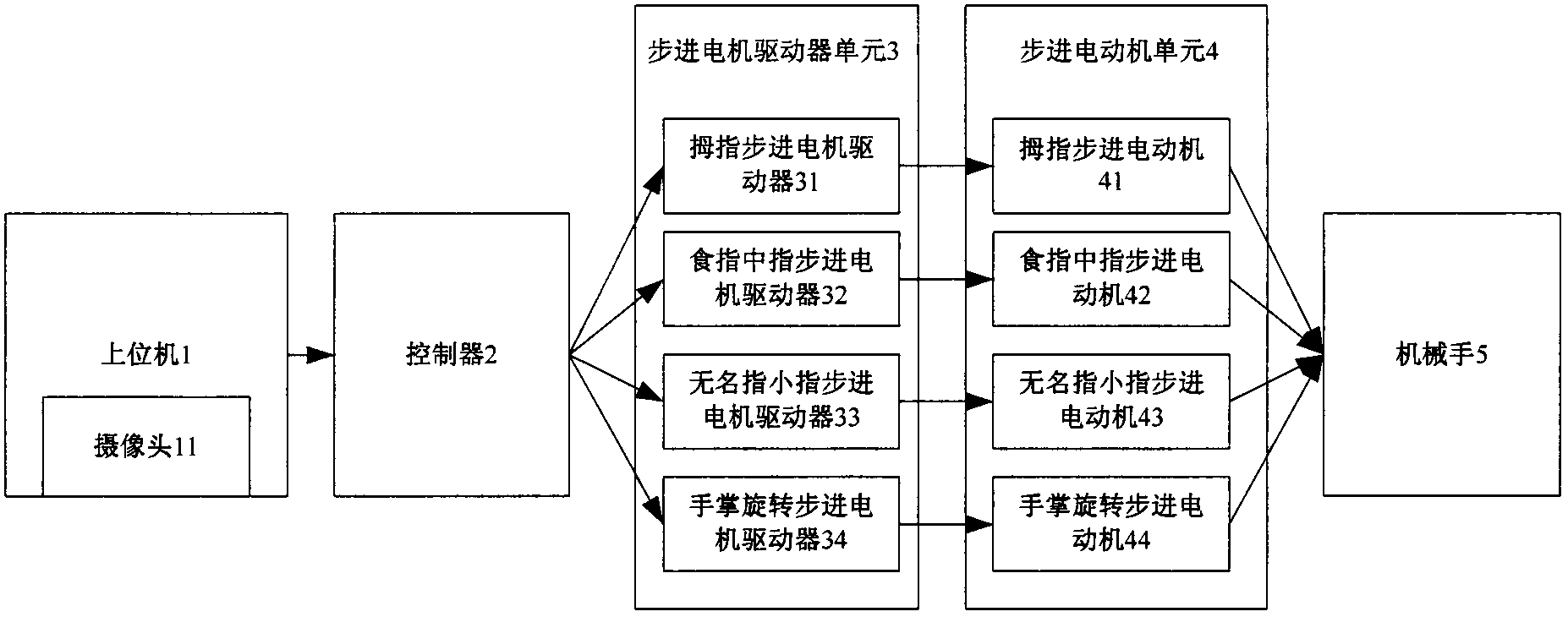
[0036] Such as figure 1 As shown, a kind of manipulator control system of the present invention includes a host computer 1, and is also provided with: a controller 2, which is used to receive the signal of the host computer 1, and send a signal to the stepper motor driver unit 3 according to the received signal Control signal; the stepper motor driver unit 3 is used to receive the control signal sent by the controller 2, and drives the stepper motor unit 4 to perform actions according to the control requirements; the stepper motor unit 4 is used for stepper motor driver unit 3 Under the drive of the control manipulator 5 stretching and rotation.

[0037] The host computer 1 includes a camera 11 for acquiring external visual signals.

[0038] Described stepper motor drive unit 3 comprises the thumb stepper motor driver 31 that drives t...


PUM


Abstract

The invention discloses a mechanical hand control system, which comprises a host machine, a controller, a step motor driver unit and a step electric motor unit, wherein the controller is used for receiving signals of the host machine and sending out control signals to the step motor driver unit according to the received signals, the step motor driver unit is used for receiving control signals sent by the controller and driving the step electric motor unit to act according to the control requirements, and the step electric motor unit is used for controlling the telescopic operation and the rotation of a mechanical hand under the driving effect of the step motor driver unit. The system adopts a visual identification method for obtaining useful control information from video images obtained by a camera and sends the useful control information to the controller, the mechanical hand is driven to act through the step motor driver and the step electric motor, the man-machine interaction, the interaction game playing and the sign language display can be realized, in addition, the object capture and rotation can be realized, and the beneficial exploration and equipment basis are provided for the research and utilization of the mechanical hand control system.

Description

technical field [0001] The invention relates to a manipulator control system. In particular, it relates to a manipulator control system with simple structure, convenient and flexible control and low cost. Background technique [0002] The research on manipulators began in the middle of the 20th century. With the development of computer and automation technology, especially with the amazing progress of computers, it developed in the direction of high speed, large capacity and low price. At the same time, the urgent need for mass production promoted It not only promotes the progress of automation technology, but also lays the foundation for the development of robots. [0003] The manipulator is mainly composed of three parts: hand, motion mechanism and control system. The hand is a part used to grasp the workpiece or tool. According to the shape, size, weight, material and operation requirements of the object to be grasped, there are various structural forms, such as clampin...

Claims


Application Information

Patent Timeline
Patent Type & Authority Applications(China)
IPC IPC(8): B25J13/08B25J15/02
Inventor 高圣伟肖成东翟文聪章立陈朝阳
Owner TIANJIN POLYTECHNIC UNIV
Why Eureka
Try Eureka