Method of maintenance and lifting for moving section flue at converter mouth

A hoisting method and the technology of the furnace mouth of the converter, which are applied in the manufacture of converters, etc., can solve the problems of maintenance personnel and the use of mechanical equipment to increase the investment in engineering maintenance costs, affect the production of the owner's factory, prolong the maintenance time, etc., and achieve the reduction of dismantling range, improving demolition efficiency, and reducing maintenance time

Active Publication Date: 2012-10-03
CHINA MCC17 GRP
View PDF1 Cites 16 Cited by
  • Summary
  • Abstract
  • Description
  • Claims
  • Application Information

AI Technical Summary

Problems solved by technology

[0002] At present, in the metallurgical converter steelmaking, it is often encountered that the active gasification flue of the furnace mouth is severely worn and needs to be replaced. Arranged between the converter and the fixed flue section, the three-dimensional space is very compact and narrow, and it is usually necessary to remove the flue support, the upper fixed flue section, the part of the process platform affected by the hoisting channel, and the connection with the fixed flue section when replacing it The medium pipeline is used to remove the hoisting and transporting channel for the movable flue at the furnace exit. The defect of this method is: in order to remove and replace the movable flue at the furnace mouth, the removed process platform and the upper flue work surface are large, and there are many parts to be removed. The large demolition scope prolongs the maintenance time, affects the production of the owner's factory, and also increases the investment in engineering maintenance costs due to the large investment in maintenance personnel and the use of mechanical equipment in the demolition working face

Method used


Image

  • Method of maintenance and lifting for moving section flue at converter mouth
  • Method of maintenance and lifting for moving section flue at converter mouth
  • Method of maintenance and lifting for moving section flue at converter mouth

Examples


Embodiment Construction

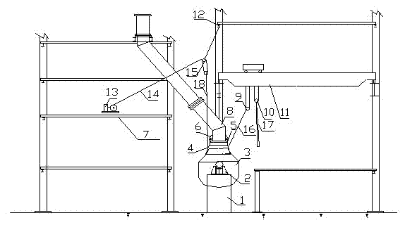
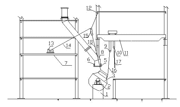
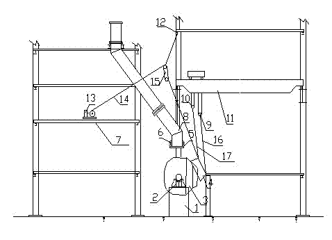
[0019] The invention provides a method for overhauling, dismantling and hoisting the flue of the active section of the furnace mouth of the converter. The construction steps are: 1. Install the hoisting pulley block and the pulley block to drive the hoisting device; 2. Arrange the hoisting steel wire rope and lifting points; 3. Remove the furnace mouth The flue lifting device of the movable section; 4. The flue of the movable section of the furnace mouth is removed. Specific steps are as follows:

[0020] 1. Set up the hoisting pulley block and the pulley block drive winch device:

[0021] The flue 4 of the movable section of the furnace mouth is arranged directly above the furnace mouth of the converter 3, and the converter 3 is supported on the converter foundation 1 through the bearing seat 2, and the converter 3 can be supported by the bearing seat 2 at 360 0 rotate. The flue 4 of the movable section of the furnace mouth is fixed on the support seat 6 of the fixed flue ...


PUM


Abstract

The invention provides a method of maintenance and lifting for a moving section flue at a converter mouth and belongs to the technical field of equipment lifting. The method includes the steps of firstly, setting a lifting pulley set and a pulley set driving and hoisting device; secondly, distributing lifting steel wire ropes and lifting spots; and thirdly, removing a lifting device for the moving section flue at the converter mouth and the mouth moving section flue. A certain movement and lifting space for the mouth moving section flue and a 360-degree rotation function of a converter are fully utilized in normal production of the converter and the mouth moving section flue, the lifting device is set and used reasonably, and accordingly upper parts of the mouth moving section flue can be moved into a converter feeding span with conveying conditions and large conveying space from the space above the converter mouth without removing the upper parts, the range of replacing and maintaining the mouth moving section flue is narrowed greatly. In addition, the method is fast and safe, removing efficiency is improved, maintenance cost is reduced, and maintenance time is reduced.

Description

technical field [0001] The invention belongs to the technical field of equipment hoisting, and in particular relates to a hoisting method for maintenance, removal, and hoisting of a flue at a movable section of a converter mouth. Background technique [0002] At present, in the metallurgical converter steelmaking, it is often encountered that the active gasification flue of the furnace mouth is severely worn and needs to be replaced. Arranged between the converter and the fixed flue section, the three-dimensional space is very compact and narrow, and it is usually necessary to remove the flue support, the upper fixed flue section, the part of the process platform affected by the hoisting channel, and the connection with the fixed flue section when replacing it The medium pipeline is used to remove the hoisting and transporting channel for the movable flue at the furnace exit. The defect of this method is: in order to remove and replace the movable flue at the furnace mouth, ...

Claims


Application Information

Patent Timeline
Patent Type & Authority Applications(China)
IPC IPC(8): C21C5/46
Inventor 朱道付程玉洲张俊周美初
Owner CHINA MCC17 GRP
Why Eureka
Try Eureka