Shallow hole drilling machine

A technology for drilling rigs and shallow holes, which is applied to rotary drilling rigs, earth-moving drilling, drilling equipment, etc., can solve the problems of reducing construction efficiency, inconvenient lifting, installation and transportation, and inconvenient transfer, transportation and lifting of shallow-hole drilling rigs. The effect of convenient transportation

Active Publication Date: 2014-09-17
河南省水利勘测有限公司
View PDF10 Cites 0 Cited by
  • Summary
  • Abstract
  • Description
  • Claims
  • Application Information

AI Technical Summary

Problems solved by technology

[0003] When in use, it is necessary to transport the independent shallow hole drilling rig and the drilling tower to the corresponding construction site through corresponding transport vehicles. Since the shallow hole drilling rig includes components such as the base, drilling assembly and internal combustion engine, the shallow hole drilling rig itself It has a large weight. During the transportation of the shallow hole drilling rig, it is necessary to use lifting equipment to lift the shallow hole drilling rig to the transport vehicle. After the shallow hole drilling rig is transported to the corresponding construction location, use the lifting equipment to lift the shallow hole drilling Unloading, the transfer, transportation and lifting of the shallow hole drilling rig are very inconvenient
At the same time, after the shallow hole drilling rig is positioned, it is necessary to use the lifting equipment to install the corresponding supporting drilling tower in a suitable position. In this way, when the drilling rod needs to be replaced, the drilling rod can be completed through the winch on the shallow hole drilling rig and the drilling tower. Replacement, and the drilling tower is very inconvenient to lift, install and transport due to its long height
Not only that, in specific exploration sites, it is usually necessary to carry out exploration and sampling on multiple sampling locations in a small area. Due to the limitations of the structure of the shallow hole drilling rig and the drilling tower itself, it is necessary to carry out frequent sampling on the shallow hole drilling rig and the drilling tower respectively. Lifting and installation not only cause high labor intensity for workers, but also greatly reduce construction efficiency

Method used


Image

  • Shallow hole drilling machine
  • Shallow hole drilling machine

Examples


Embodiment Construction

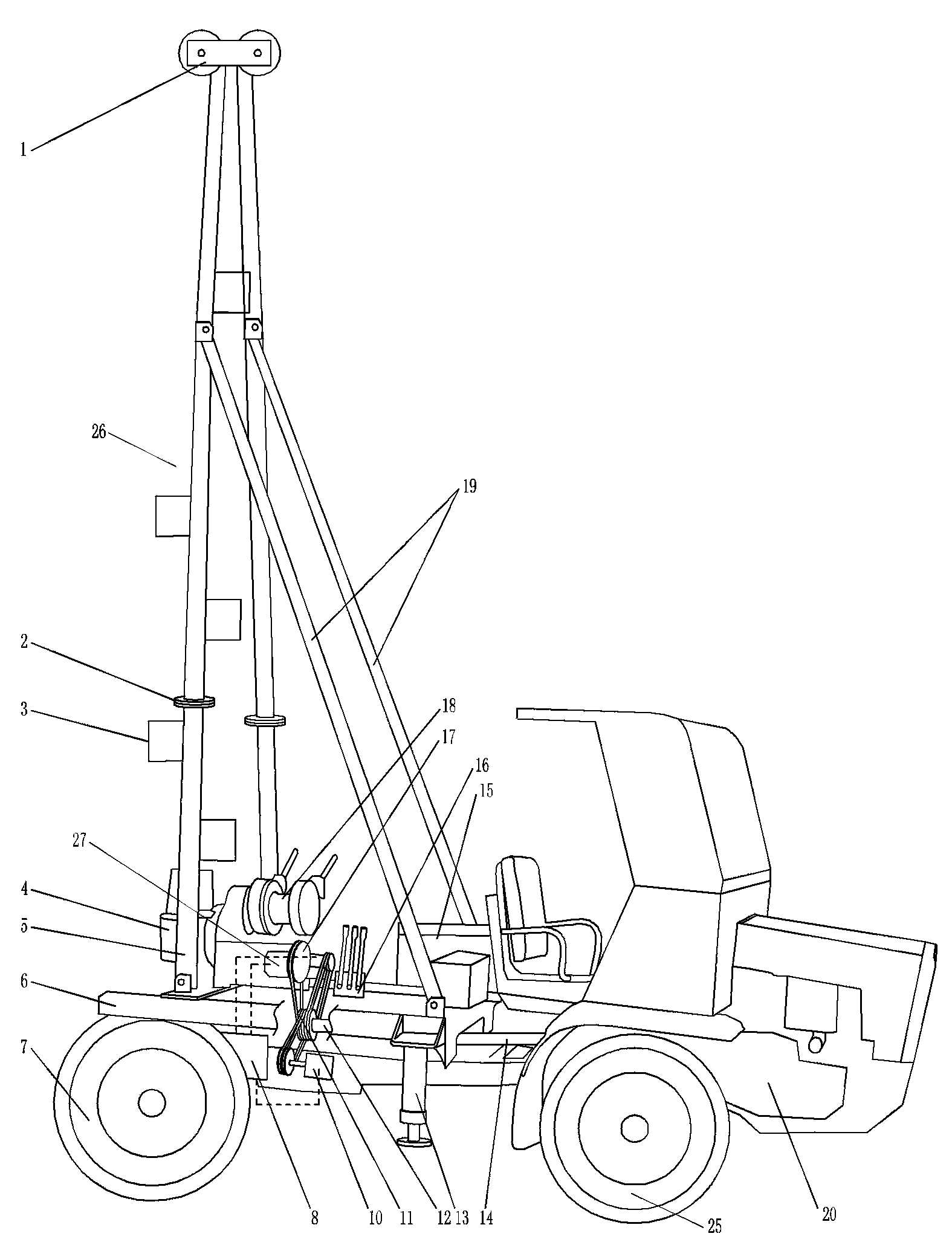
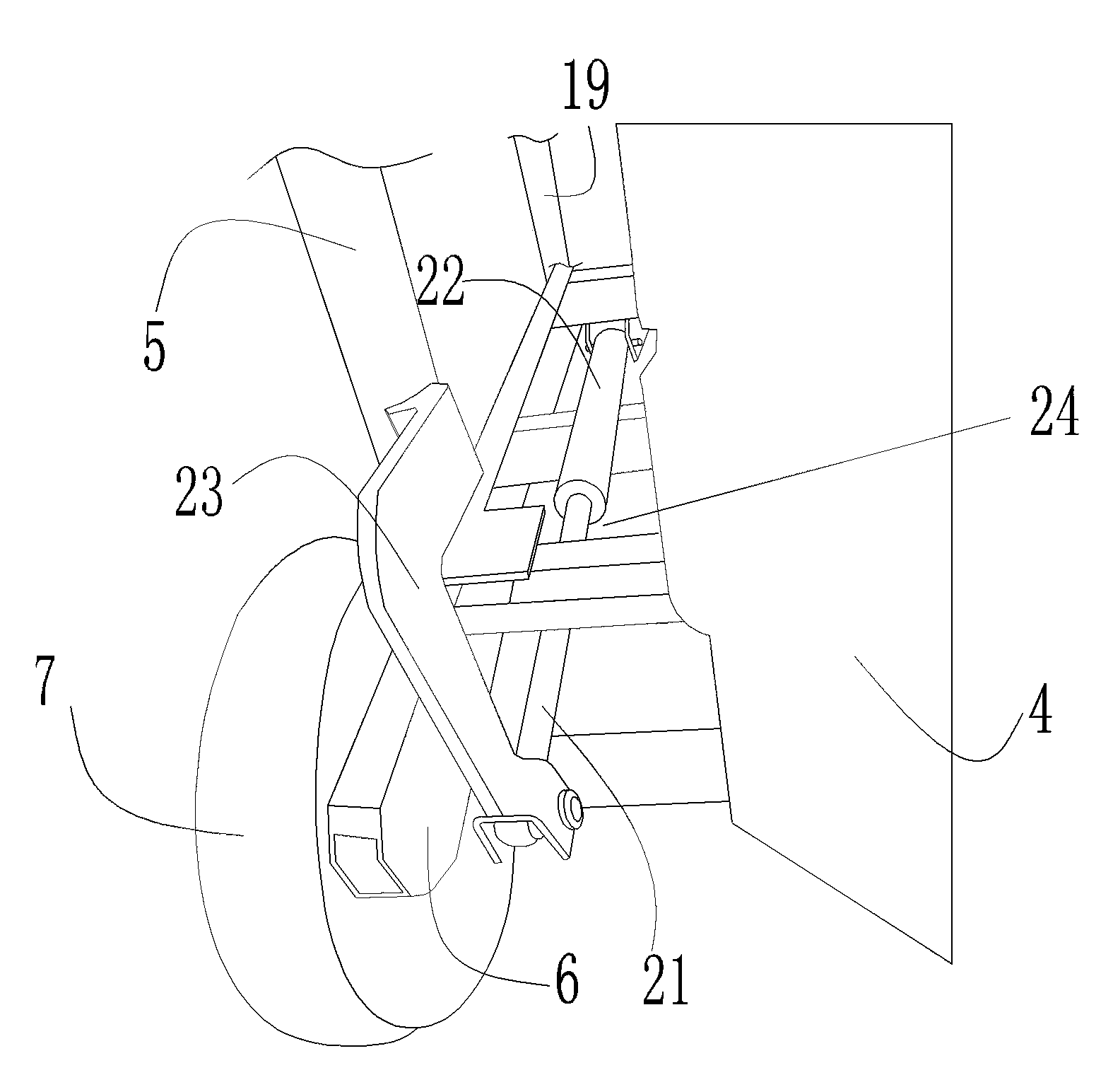
[0020] An example of a shallow hole drilling machine Figure 1~2 Shown: comprise the car body that has automatic driving function, and car body comprises chassis 6, and the front end of chassis 6 is equipped with internal combustion engine 20 and the transfer mechanism that the power input end is connected with the power output end of internal combustion engine 20, and the transfer mechanism is divided by the internal combustion engine. The transfer mechanism has a walking and drilling power output end, the chassis 6 is also provided with a front road wheel 25 and a rear road wheel 7, and the walking power output end of the transfer mechanism is connected to the front road wheel 25 through the road wheel transmission mechanism. Transmission connection, so as to realize the self-driving function of the chassis. The upper end of the chassis 6 is provided with a drilling assembly, a drilling tower 26 and a hydraulic drive mechanism. The drilling assembly includes a vertical shaft...


PUM


Abstract

The invention relates to a shallow hole drilling machine. The shallow hole drilling machine comprises a vertical shaft type revolution device, a chassis with travelling wheels, and a transfer gear of which the power input end is in drive connection with the power output end of an internal combustion engine; the internal combustion engine is arranged on the chassis; the transfer gear has travelling and drilling power output ends; the travelling power output end of the transfer gear is in drive connection with the traveling wheel through a travelling wheel drive mechanism; the drilling power output end of the transfer gear is in driven connection with the power input end of the vertical shaft type revolution device through a drilling drive mechanism; and the vertical shaft type revolution device is fixed on the chassis. The invention provides the shallow hole drilling machine which is convenient to transfer.

Description

technical field [0001] The invention relates to the field of drilling rigs, in particular to a shallow hole drilling rig for geological exploration. Background technique [0002] Shallow hole drilling rigs are the main construction equipment mainly based on engineering geology and supplemented by core drilling. Well and core drilling. As a vertical shaft drilling rig, the shallow hole drilling rig includes a base and an internal combustion engine on it and a drilling assembly. The drilling assembly includes a vertical shaft gyrator used The hoist is used to cooperate with the corresponding independent drilling tower to complete the rod changing construction of the drilling process. The top of the drilling tower matched with the hoist is equipped with a pulley block, and the drum of the hoist is wound with a winding pulley block that can be hoisted after reversing the direction. Corresponding wire rope for drill pipe. The power output end of the internal combustion engine ...

Claims


Application Information

Patent Timeline
Patent Type & Authority Patents(China)
IPC IPC(8): E21B7/02E21B3/02E21B15/00
Inventor 赵健仓彭新生张培存刘东雨
Owner 河南省水利勘测有限公司
Why Eureka
Try Eureka