Hydraulic synchronous system for realizing load balance based on proportional relief valve

A technology of proportional relief valve and hydraulic synchronization, which is applied in the direction of fluid pressure actuators, servo motors, mechanical equipment, etc., can solve the problems of inability to control load balance, inability to achieve speed synchronization, and inability to synchronize, so as to eliminate adverse effects , The output torque is consistent and the effect of eliminating synchronization error

Inactive Publication Date: 2012-10-03
CENT SOUTH UNIV
View PDF8 Cites 20 Cited by
  • Summary
  • Abstract
  • Description
  • Claims
  • Application Information

AI Technical Summary

Problems solved by technology

[0003] The existing hydraulic system closed-loop synchronous control technology often adopts the equivalent mode and the master-slave mode, but they cannot regulate the load balance in the driving process, and cannot fundamentally solve the synchronization problem under the condition of unbalanced load
In the Chinese invention patent CN101749294A announced on June 23, 2010, a hydraulic synchronous drive control system for load balancing is disclosed. Balanced, speed synchronization in the true strict sense cannot be achieved, and better coordination and consideration is needed between load balancing and speed synchronization drivers

Method used


Image

  • Hydraulic synchronous system for realizing load balance based on proportional relief valve
  • Hydraulic synchronous system for realizing load balance based on proportional relief valve

Examples


Embodiment Construction

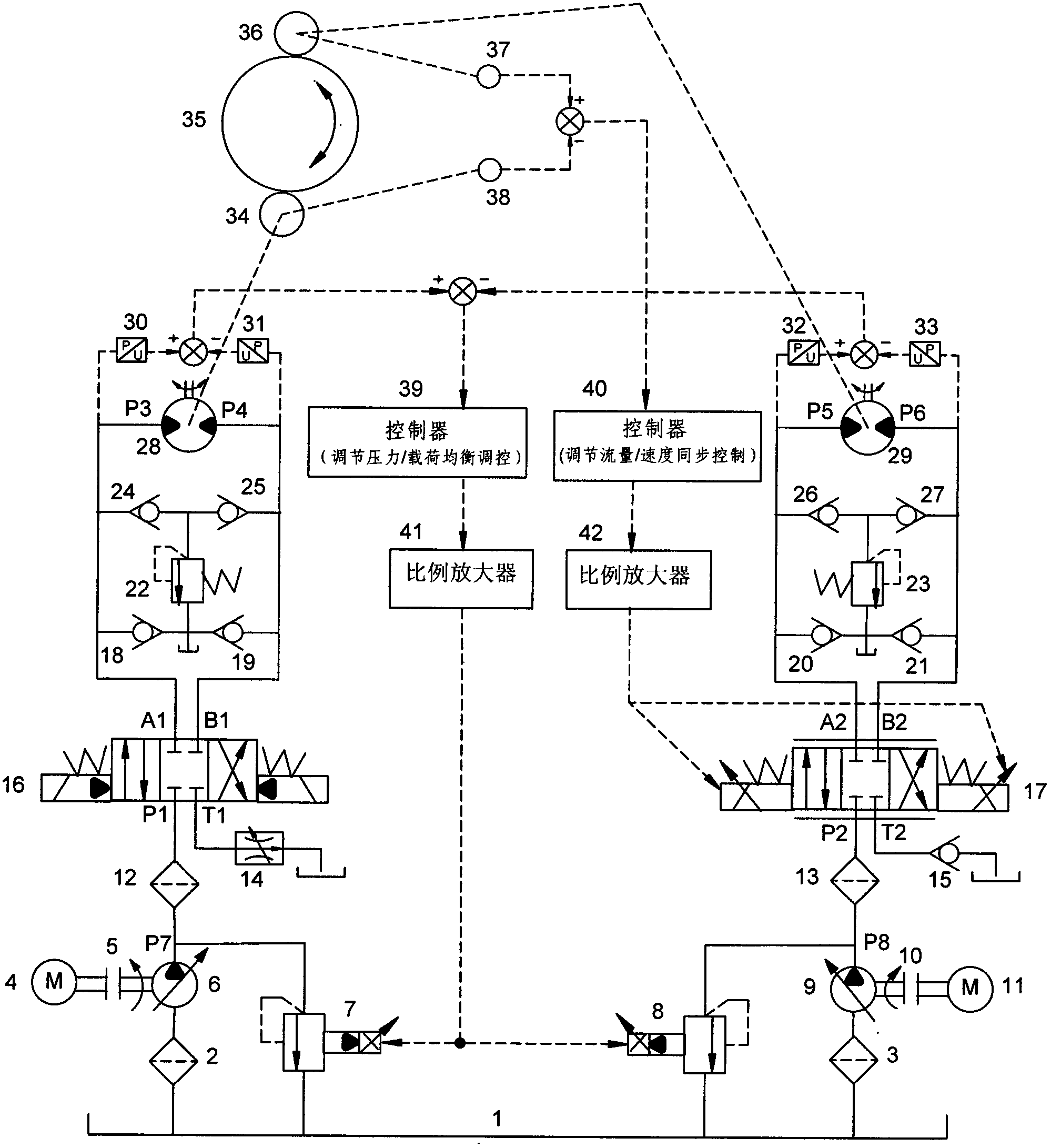
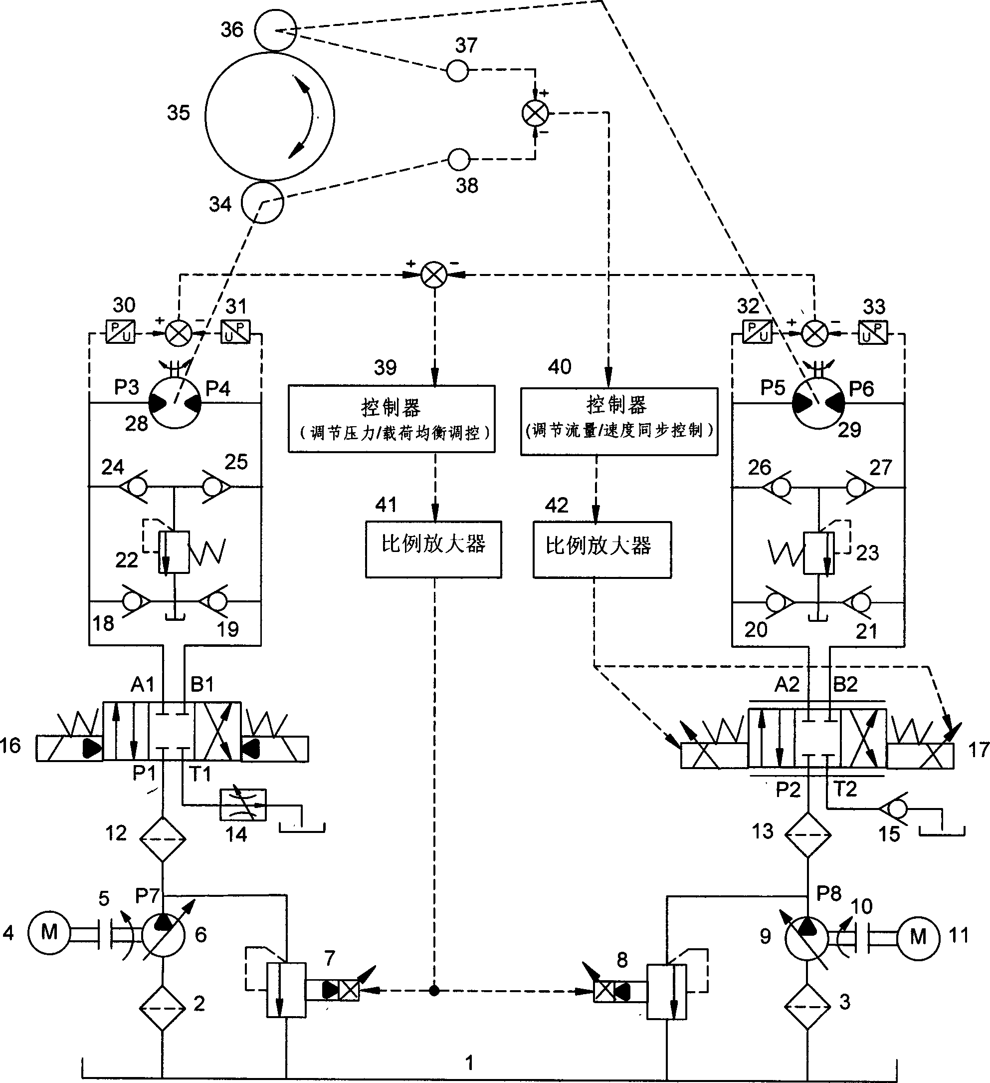
[0012] As shown in the accompanying drawings, the present invention includes a hydraulic transmission circuit and an electro-hydraulic control system. The hydraulic transmission circuit includes an oil tank 1, two filters 2, 3, two fine filters 12, 13, two motors 4, 11, two shaft couplings 5, 10, two variable displacement pumps 6, 9, Two proportional overflow valves 7, 8, speed control valve 14, three-position four-way electro-hydraulic directional valve 16, three-position four-way proportional directional valve 17, nine one-way valves 15, 18, 19, 20, 21, 24, 25, 26, 27, two overflow valves 22, 23, two bi-directional hydraulic motors 28, 29, two pinion gears 34, 36, large gear 35; the first motor 4 passes through the first coupling 5 is connected to the first variable pump 6; the oil inlet of the first filter 2 is connected to the oil tank 1, and the oil outlet is connected to the oil inlet of the first variable pump 6; the oil outlet of the first variable pump 6 P7 is respec...


PUM


Abstract

The invention discloses a hydraulic synchronous system for realizing load balance based on a proportional relief valve. The system comprises a hydraulic transmission loop and an electro-hydraulic control system and aims to realize high-precision synchronous motion on a condition of unbalance load; the hydraulic transmission loop comprises an oil case, a filter, a fine filter, a motor, a coupler, a variable capacity pump, a speed regulating valve, an electro-hydraulic reversing valve, a proportional relief valve, a proportional reversing valve, a one-way valve, a relief valve, dual-way hydraulic motors, a small gear and a large gear; and the electro-hydraulic control system comprises a speed synchronous control loop based on speed feedback and a load balance regulation and control loop based on pressure feedback. According to the invention, working pressure of hydraulic motors is directly regulated and controlled by the proportional relief valve specifically to a working condition of unbalance load, so that the load balance between different hydraulic motors is realized; the hydraulic synchronous system radically eliminates negative influence of the unbalance load on synchronous precision and realizes coordination between speed synchronization and load balance; and relatively high synchronous precision is acquired.

Description

technical field [0001] The invention relates to a fluid pressure actuator, in particular to a hydraulic synchronous system based on a proportional overflow valve to realize load balance. Background technique [0002] The hydraulic synchronous drive system is mainly aimed at high-load and high-power applications. Two or more hydraulic motors or hydraulic cylinders drive a load at the same time. This kind of synchronous drive of multiple actuators, due to the influence of factors such as manufacturing accuracy, installation error, friction, load, etc., inevitably has the problem of asynchronous motion. In actual work, the load borne by the actuators often changes, and the loads between each actuator are not equal at the same time. This unbalanced load, that is, the partial load, is likely to cause motion synchronization accuracy errors of the synchronous actuators. , and generally unavoidable. Especially for some high-power hydraulic synchronous drive systems with complex wo...

Claims


Application Information

Patent Timeline
Patent Type & Authority Applications(China)
IPC IPC(8): F15B11/22
Inventor 金耀夏毅敏
Owner CENT SOUTH UNIV
Why Eureka
Try Eureka