Radar with anti-interference and multi-target identification functions and detection method thereof

A detection method and multi-target technology, applied to radio wave measurement systems, instruments, etc., can solve problems such as mutual interference and misjudgment

Inactive Publication Date: 2014-06-04
BEIJING INSTITUTE OF TECHNOLOGYGY +2
View PDF7 Cites 4 Cited by
  • Summary
  • Abstract
  • Description
  • Claims
  • Application Information

AI Technical Summary

Problems solved by technology

[0009] The purpose of the present invention is to solve the problem of misjudgment caused by mutual interference when multiple radars of the same frequency band and system are used, and to provide a car anti-collision radar with functions of anti-mutual interference and multi-target recognition and its detection method

Method used


Image

  • Radar with anti-interference and multi-target identification functions and detection method thereof
  • Radar with anti-interference and multi-target identification functions and detection method thereof
  • Radar with anti-interference and multi-target identification functions and detection method thereof

Examples


Embodiment 1

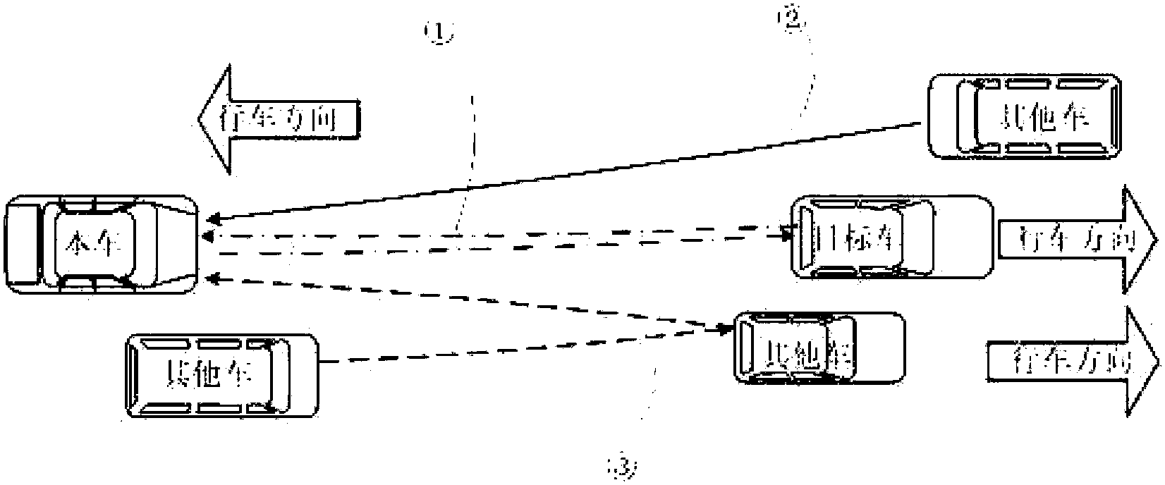
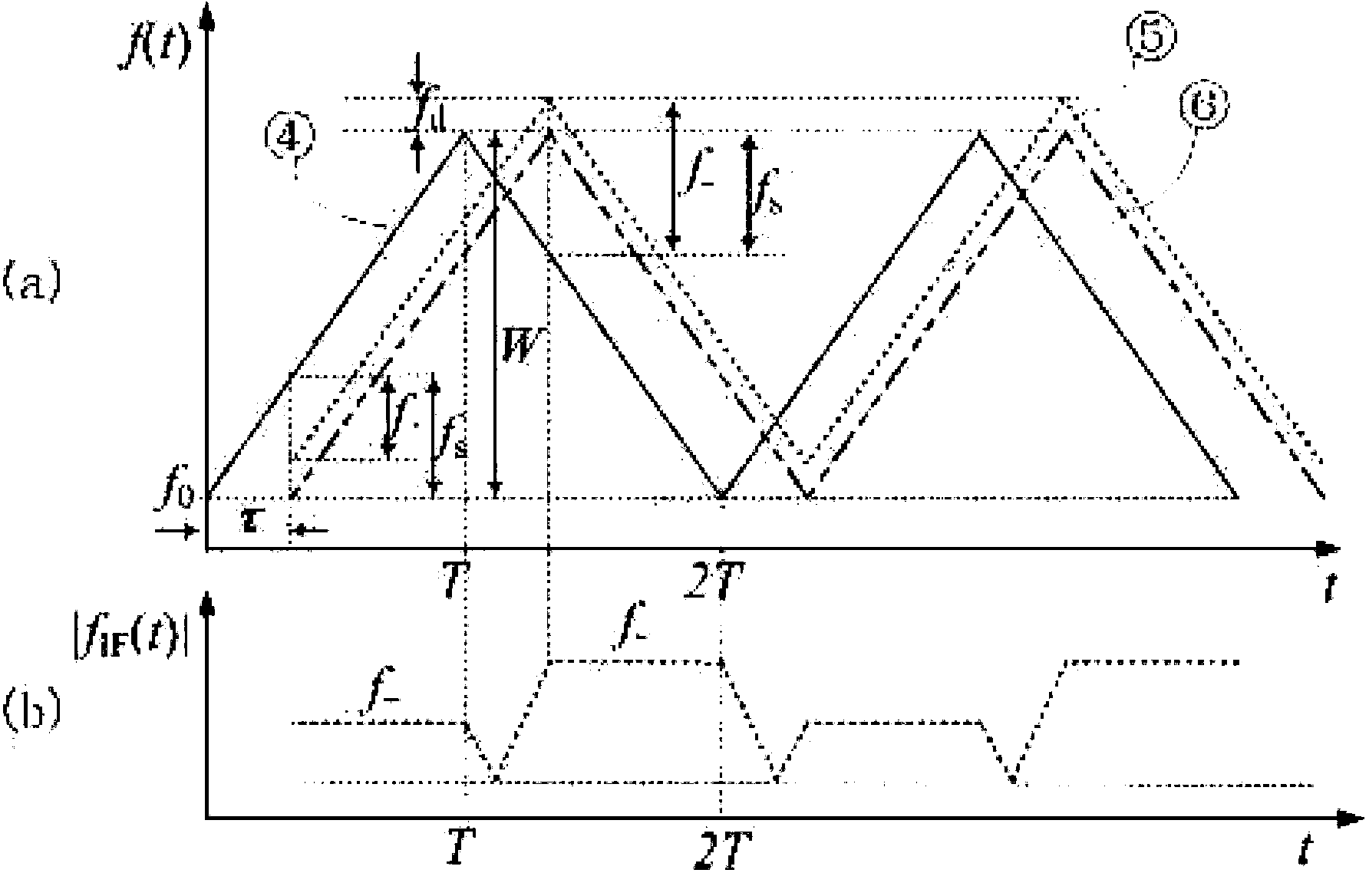
[0063] Figure 4 (a) is the modulated waveform and echo signal diagram generated by the radar waveform generator in Embodiment 1, the abscissa is time, and the ordinate is instantaneous frequency. Each small period of the modulation waveform contains three segments, which are: from the start frequency f 0 Tuned up to frequency f j The upper sweep phase AB, the constant frequency phase BC and the slave frequency f j Tuned down to frequency f 0 The lower sweep stage CD. The constant frequency f j In each large cycle, it changes randomly within the predetermined design working bandwidth. If there are M small periods in one large period, then j=1, 2, L, M. For this embodiment, the FM bandwidth W1 , W 2 , L, W M are random changes. When the transmitted electromagnetic wave encounters a target with a distance of R and a speed of v, the echo signal is the delay of the transmitted signal, and each corresponding small cycle also includes three segments: the upper sweep phase A...

Embodiment 2

[0069] Figure 6 (a) is the modulation waveform and echo signal generated by the radar waveform generator in Embodiment 2, the abscissa is time, and the ordinate is instantaneous frequency. Each small period of the modulation waveform contains three segments, which are: from the start frequency f 0 Tuned down to frequency f j The down-sweep phase AB, the constant frequency phase BC and the slave frequency f j Tuned up to frequency f 0 The upper sweep stage CD. The constant frequency f i In each large cycle, it changes randomly within the predetermined design working bandwidth. If there are M small periods in one large period, then j=1, 2, L, M. For this embodiment, the FM bandwidth W 1 , W 2 , L, W M is randomly changed. The echo signal is mixed, filtered, and amplified to obtain an intermediate frequency signal|f IF (t)|, such as Figure 6 as shown in (b), Figure 6 (b) is an intermediate frequency signal diagram generated by the radar waveform generator in the p...


PUM


Abstract

The invention relates to a car anti-collision radar with anti-interference and multi-target identification functions and a detection method thereof, belonging to the technical field of radar communication and the field of car electronics. The radar device and the detection method thereof not only can be used for measuring the distance and the relative speed of a target, but also can be used for identifying a plurality of targets in a complex environment and eliminating false targets; particularly, under the condition of simultaneous use of a plurality of radars with the same frequency range and the same system in a detection range, mutual interference among the radars can be suppressed so as to correctly judge a real target; and a modulation waveform of the radar is a major cycle TB repetitive waveform combined by a plurality of minor cycle TL modulation waveforms according to a random principle, and different radars are configured with different modulation waveforms in the major cycle, so interference signals of other radars can be analyzed out by a signal processing circuit so as to suppress interference and eliminate error detection caused by the interference.

Description

technical field [0001] The invention relates to an automobile anti-collision radar with anti-jamming and multi-target recognition functions and a detection method thereof, belonging to the technical field of radar communication and the field of automobile electronics. Background technique [0002] The radar emits electromagnetic waves to irradiate the target and receives its echo, and obtains information such as the distance and relative speed of the target according to the time difference (delay) and frequency change (Doppler frequency) between the echo and the transmitted wave. However, when multiple radars are used simultaneously within the detection range, such as automotive anti-collision radars or automotive adaptive cruise control radars, if they use the same frequency band and the same system (for example, both use 76GHz FMCW radar) , there will be mutual interference between multiple radars coexisting. If the corresponding processing is not carried out on the equipm...

Claims


Application Information

Patent Timeline
Patent Type & Authority Patents(China)
IPC IPC(8): G01S7/36G01S7/40
Inventor 卜祥元范远璋安建平李安培邵立伟张军卢继华
Owner BEIJING INSTITUTE OF TECHNOLOGYGY
Why Eureka
Try Eureka