Method and device for automatically demolding commutator injection-compression mold

A technology of automatic demolding and commutator, applied in the direction of commutator manufacturing, etc., can solve the problems of increasing production cost, low work efficiency, limited quantity and specification of commutator segment components, etc., so as to improve work efficiency and reduce labor intensity. , the effect of reducing production costs

Inactive Publication Date: 2012-10-03
瑞安市博诺机电有限公司
View PDF5 Cites 17 Cited by
  • Summary
  • Abstract
  • Description
  • Claims
  • Application Information

AI Technical Summary

Problems solved by technology

The existing release method and device of the commutator injection mold are manual release after the injection is completed, which completely relies on manual beating to separate the upper, middle, and lower templates, and the labor intensity of the operators is high and the work efficiency is low. , and the quantity and specification of the injected commutator segments are limited, which also increases the production cost

Method used


Image

  • Method and device for automatically demolding commutator injection-compression mold
  • Method and device for automatically demolding commutator injection-compression mold
  • Method and device for automatically demolding commutator injection-compression mold

Examples


Embodiment Construction

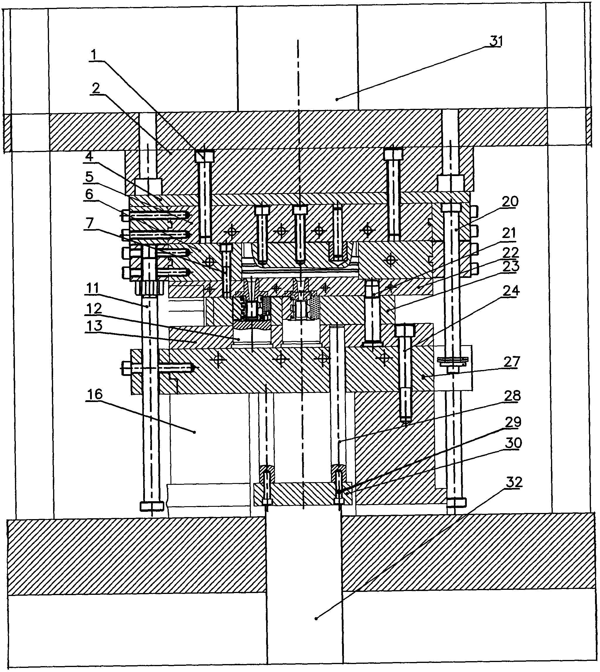
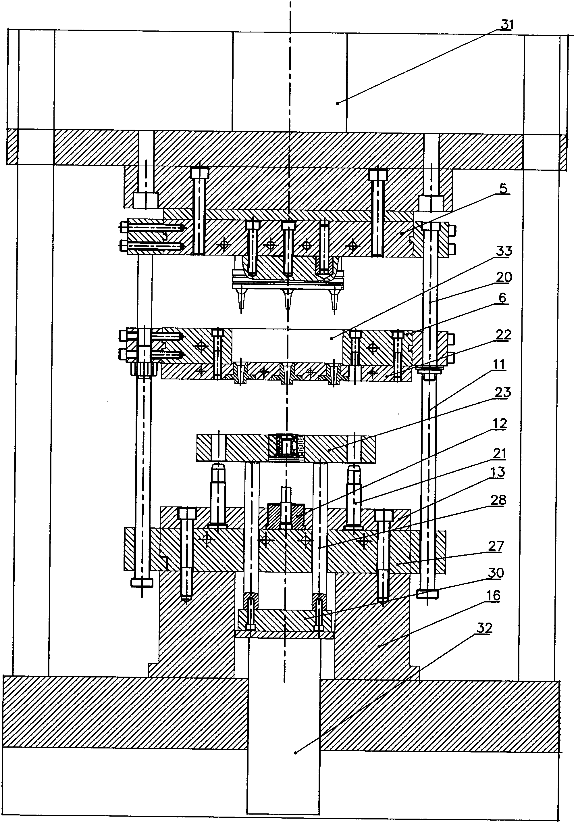
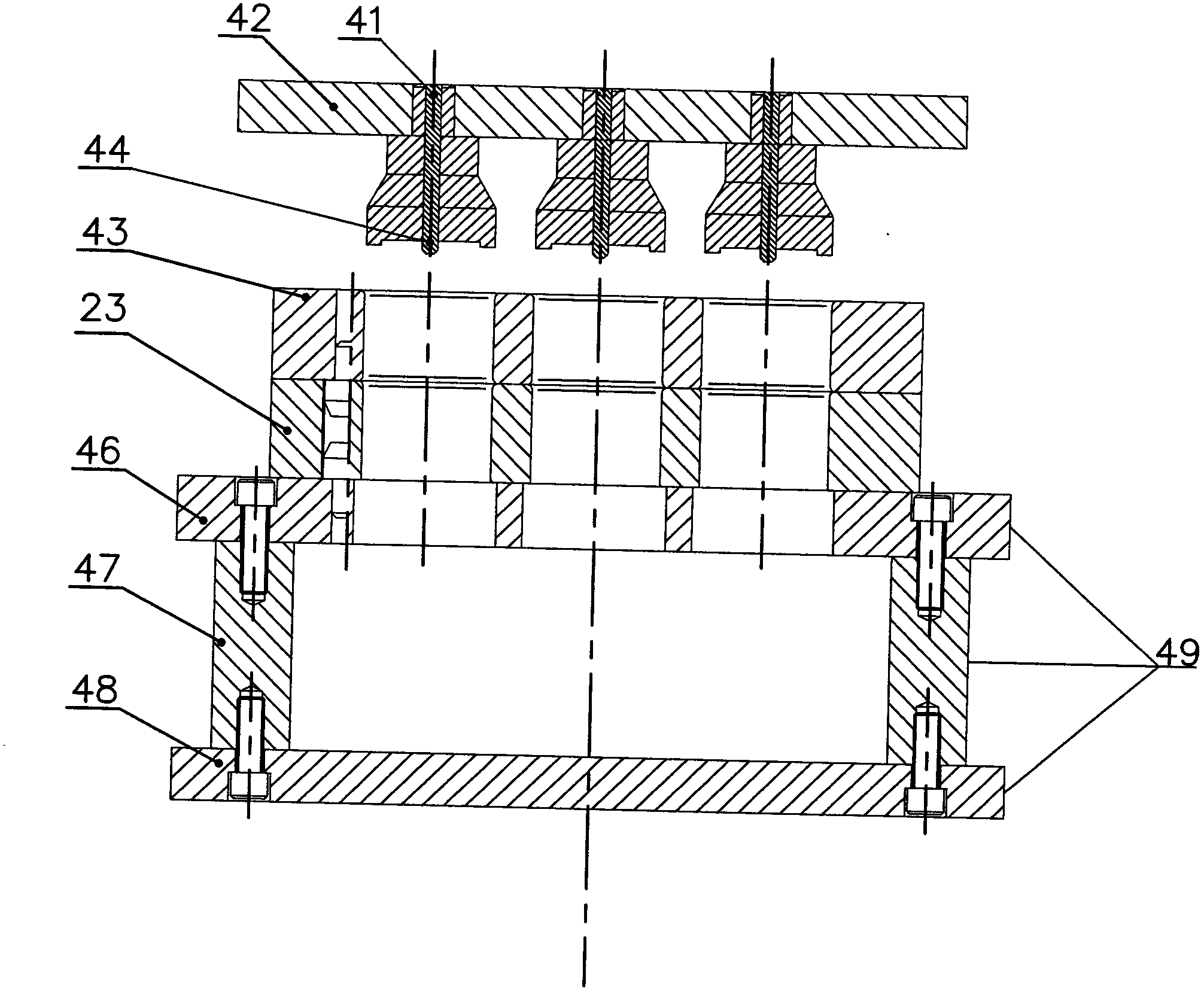
[0010] The present invention will be further described in detail below in conjunction with the accompanying drawings and embodiments.

[0011] refer to Figure 1 to Figure 3 It can be seen that when carrying out the production process of commutator injection molding, the automatic demoulding method of commutator injection mold of the present invention is: first, in the material chamber of material chamber plate, fill molding compound (also known as bakelite powder) , Install the commutator segment assembly in the middle mold of the middle template (the plastic core, rubber ring, etc. have been removed), and then mold the heating plate, material chamber plate, upper mold, middle mold and lower mold (the material chamber plate and the upper mold) template has been connected as a whole), fill the inside of the commutator segment assembly with molding compound and injection molding (it has been cured to form a commutator semi-finished product); then, the upper oil cylinder is firs...


PUM


Abstract

The invention relates to a method for automatically demolding a commutator injection-compression mold, comprising the steps of: loading a molding material into a material compartment plate, arranging commutator segment components in a middle mold of a middle template, performing mold closing on a heating plate, the material compartment plate, an upper template, the middle template and a lower template, filling the molding material into the commutator segment components and performing injection-compression molding; and then, separating the heating plate and the upper template from an upper oil cylinder and supporting the separated heating plate and upper template by a suspender, separating the upper template and the lower template and supporting the separated upper template and lower template by a pull rod, jacking the middle template by ejector rods driven by a lower oil cylinder so as to separate the middle template and the lower template, taking out the middle template, and jacking out a semi-finished product of the commutator in the middle template by a delivery foot on an injection-compression demolding frame. A device for automatically demolding the commutator injection-compression mold is characterized in that the heating plate is connected with the upper oil cylinder, the lower template and a base plate are provided the ejector rods in contact with the middle template, and the ejector rods are connected with the lower oil cylinder; the suspender is arranged between the material compartment plate and the heating plate, and the pull rod is arranged between the base plate and the material compartment plate. The method and the device disclosed by the invention has the advantages of realizing automatic operation of demolding, reducing labor intensity and increasing working efficiency; and the specification or quantity of the commutator segment components on the middle template can be increased properly.

Description

technical field [0001] The invention relates to a demoulding method and device for an injection mold used in the production process of a motor commutator. Background technique [0002] At present, the motor commutator includes commutator segments, molding compounds, bushings, etc. In its production process, it is necessary to perform injection molding on the internal filling molding compound of the commutator segment components to make commutator semi-finished products. The existing release method and device of the commutator injection mold are manual release after the injection is completed, which completely relies on manual beating to separate the upper, middle, and lower templates, and the labor intensity of the operators is high and the work efficiency is low. , and the quantity and specification of the injected commutator segments are limited, which also increases the production cost. Contents of the invention [0003] The object of the present invention is to overco...

Claims


Application Information

Patent Timeline
Patent Type & Authority Applications(China)
IPC IPC(8): H01R43/06
Inventor 林宣快谢丙利徐顺建何长林朱建伟
Owner 瑞安市博诺机电有限公司
Why Eureka
Try Eureka