
Synchronization signal transmission method applied to large-scale antenna array

A large-scale antenna and synchronization signal technology, applied in the direction of space transmit diversity, diversity/multi-antenna systems, etc., can solve the problems of unsuitable transmit antennas, complex synchronization algorithms, and long synchronization time, so as to avoid low power utilization and realize Effects with low complexity

Inactive Publication Date: 2012-10-03
HUAWEI TECH CO LTD
View PDF5 Cites 22 Cited by
  • Summary
  • Abstract
  • Description
  • Claims
  • Application Information

AI Technical Summary

Problems solved by technology

TSTD uses only one transmitting antenna at the same time to form an omnidirectional signal, but when the number of antennas is large, its utilization rate of transmitting power is too low to ensure that users can obtain a reliable receiving signal-to-noise ratio
PVS uses beams that are complementary to each other in space at different times to achieve coverage of the space area. To obtain a reliable signal-to-noise ratio, it is necessary to combine multiple received signals. When the number of antennas is large, the synchronization time will be too long. long
CDD transmits synchronization signals that are cyclically shifted to each other on different antennas to ensure omnidirectional characteristics, but it will bring pseudo multipath effects at the receiving end, and the corresponding synchronization algorithm is more complicated
Therefore, the existing synchronous signal transmission method cannot be applied to large-scale antenna arrays with a large number of transmitting antennas

Method used


Image

  • Synchronization signal transmission method applied to large-scale antenna array
  • Synchronization signal transmission method applied to large-scale antenna array
  • Synchronization signal transmission method applied to large-scale antenna array

Examples


Embodiment Construction

[0021] The present invention will be further described below in conjunction with accompanying drawing and specific embodiment:

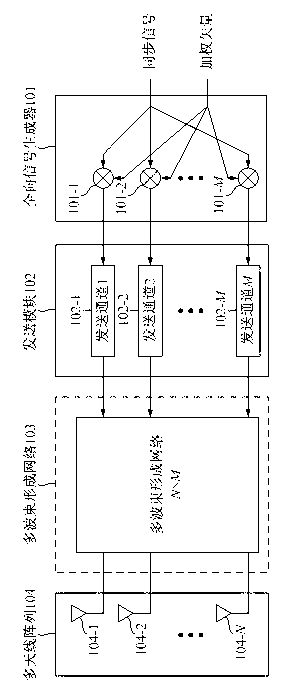
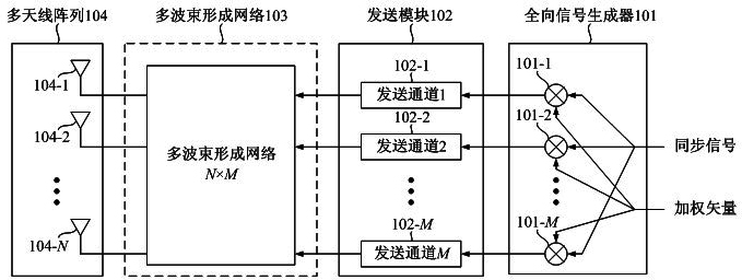
[0022] Synchronous signal transmission methods using large-scale antenna arrays such as figure 1 shown. The synchronization signal transmission process is as follows:

[0023] The base station first generates the original synchronization signal. The sequence used by this signal and its baseband modulation mode (such as single-carrier or multi-carrier modulation) can be selected depending on the situation, and the present invention does not impose any restrictions on it.

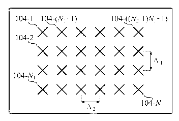
[0024] The generated synchronization signal is sent to the omnidirectional signal generator 101 together with the weighted vector. The main function of the omnidirectional signal generator 101 is to make the synchronization signal finally sent from the multi-antenna array 104 have omnidirectional characteristics. The omnidirectional signal generator 101 mainly includes M multipl...


PUM


Abstract

The invention discloses a synchronization signal transmission method applied to a large-scale antenna array. The method comprises the following steps that: (a) an antenna array of a base station is configured into a one-dimensional linear array or a two-dimensional rectangular array; (b), the base station generates an original synchronization signal, maps the original synchronization signal to each antenna or each beam port by using a weighted vector, and transmits the mapped synchronization signal from each antenna; and (c) low-correlation weighted vectors can be used for realizing transmission diversity at different moments. When the antenna array of the base station is the one-dimensional linear array or the two-dimensional rectangular array, the original synchronization signal can be mapped to each antenna or each beam port by using a cyclical orthogonal sequence as the weighted vector, and the omnibearing coverage of the synchronization signal in a current cell (or a sector) can be realized; the method is low in implementation complexity and universal for different scenarios; and transmitted power can be maximally utilized, and the omnibearing coverage can be realized within a short time.

Description

technical field [0001] The invention relates to a mobile communication system using a large-scale antenna array on the base station side, in particular to realizing the transmission of synchronous signals in the large-scale antenna array. Background technique [0002] In order to meet the needs of future development, the mobile communication system is required to be able to support high-speed packet data transmission of hundreds of megabits or even gigabits per second. In the case of increasingly tight wireless spectrum resources, multi-antenna transmission and multi-antenna reception (MIMO ) wireless transmission technology has been one of the mainstream technologies in the field of mobile communication research for more than ten years. Limited by the number of antennas (taking 3GPP's LTE-A as an example, it supports up to 8 transmission antennas on the base station side), the spectrum efficiency of traditional MIMO technology is still low, so more antenna configurations ar...

Claims


Application Information

Patent Timeline
IPC IPC(8): H04B7/06
Inventor 高西奇孟鑫江彬仲文
Owner HUAWEI TECH CO LTD
Learn More