Data transmission system, data interface device and data transmission method for multiple servers

A technology of data transmission system and data interface, applied in the direction of digital transmission system, selection device of multiplexing system, transmission system, etc., can solve the problem of large business delay between multi-hop equipment, not supporting different products, core switching equipment High cost problem, to achieve the effect of increasing network throughput, solving compatibility problems, and increasing deployment flexibility

Active Publication Date: 2012-10-03
XFUSION DIGITAL TECH CO LTD
View PDF2 Cites 5 Cited by
  • Summary
  • Abstract
  • Description
  • Claims
  • Application Information

AI Technical Summary

Problems solved by technology

This kind of tree structure has many disadvantages: on the one hand, the use of two-layer or three-layer multi-layer superposition architecture has disadvantages such as high cost of core switching equipment, large service delay between multi-hop devices, and limited flexibility; On the other hand, most traditional data centers use Ethernet transmission technology, and the throughput rate of data transmission is relatively limited; on the other hand, traditional data centers do not have a unified control and management plane, and cannot consider data flow from the perspective of the entire network topology scheduling
[0005] However, first, the three components of the data transmission system must use the same series of supporting equipment, and the networking process does not support different products produced by different manufacturers, that is, the compatibility of the data transmission system is poor; second, Although this data transmission system can achieve one-hop reachability between any node and another node, it still cannot meet the demand for data transmission speed in some cases; third, the networking cost of applying this data center is relatively high

Method used


Image

  • Data transmission system, data interface device and data transmission method for multiple servers
  • Data transmission system, data interface device and data transmission method for multiple servers
  • Data transmission system, data interface device and data transmission method for multiple servers

Examples


Embodiment 1

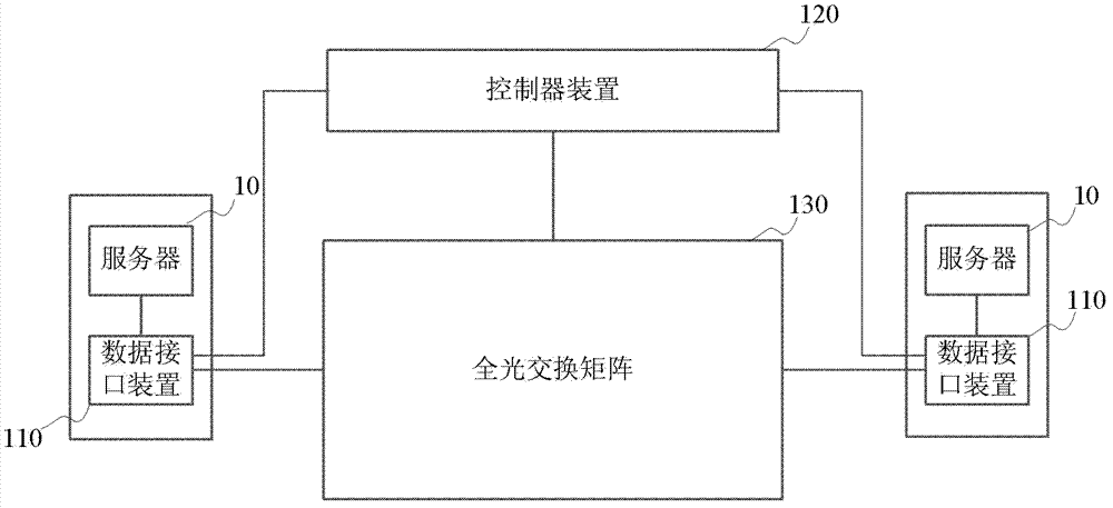
[0038] Please refer to figure 1 , which shows a structural block diagram of a data transmission system between multiple servers provided by Embodiment 1 of the present invention, the data transmission system includes a data interface device 110 arranged at each server 10 end, and a A controller device 120 and an all-optical switch matrix 130 connected to the data interface device 110 and the controller device 120 respectively.

[0039] The data interface device 110 is used to receive the data flow from the server 10, and generate a forwarding request according to the received data flow. The forwarding request may include information such as source address, destination address, and data size of the data flow. In specific implementation, the data interface device 110 can be implemented as a data card, which can be connected to the server 10 through the PCI Express bus interface, and can also be connected to the control device 120 through the Ethernet interface, or can be connect...

Embodiment 2

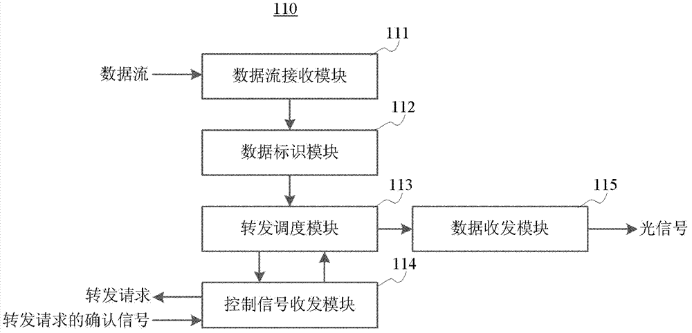
[0059] Please refer to Figure 5 , which shows a structural block diagram of the data interface device provided by Embodiment 2 of the present invention. The data interface device includes a data flow receiving module 510 , a data identification module 520 , a forwarding scheduling module 530 , a control signal transceiving module 540 and a data transceiving module 550 .

[0060] The data stream receiving module 510 is used for receiving the data stream from the server connected to it. Since each data interface device is connected to a server, the data stream receiving module 520 can receive the data stream from the server connected to it, and the data stream receiving module 510 can be implemented by using the PCI Express bus interface and related protocols.

[0061] The data identification module 520 is configured to generate corresponding flow identification information according to the data stream received by the data stream receiving module 510 . Flow identification inf...

Embodiment 3

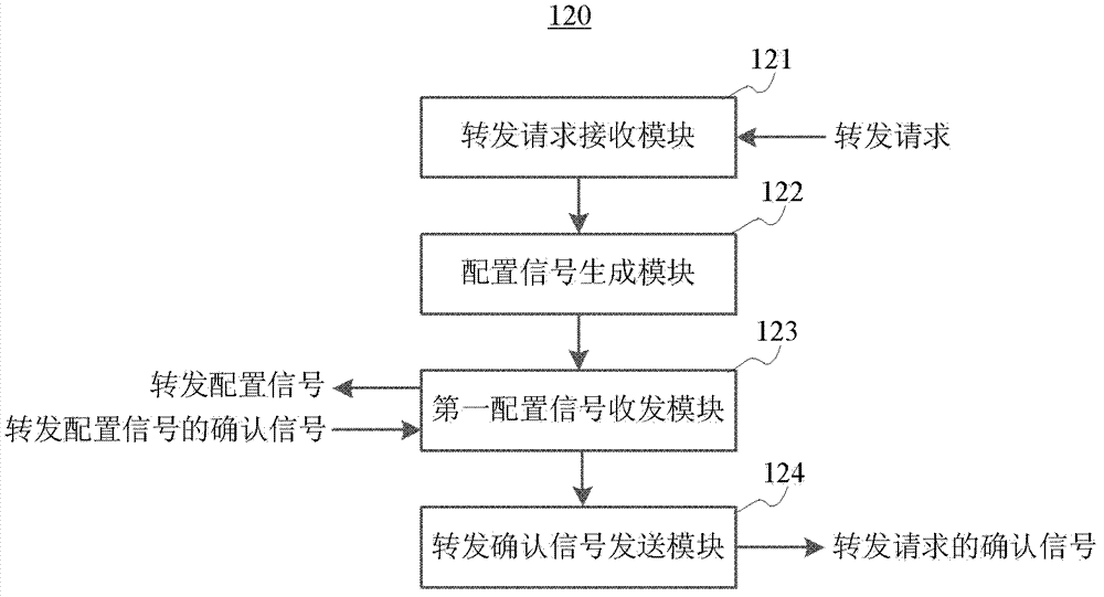
[0074] In order to enhance the deployment flexibility of the data transmission system, the controller device may also employ distributed control logic. The distributed control logic can be composed of at least two or even multiple controller devices, each controller device can be connected to several data interface devices, and each controller device is also connected to each other. Please refer to Figure 6 , which shows a structural block diagram of the controller device provided in Embodiment 3 of the present invention. The controller device 600 may include a forwarding request receiving module 610 , a configuration signal generating module 620 , a first configuration signal transceiving module 630 and a forwarding confirmation signal sending module 640 .

[0075] The forwarding request receiving module 610 is used to receive the forwarding request sent by the data interface device, and the forwarding request usually includes information such as source address, destination...


PUM


Abstract

The invention discloses a data transmission system, a data interface device and a data transmission method for multiple servers, belonging to the field of network communication. The data transmission system comprises a data interface device, a controller device and a full gloss exchange matrix, wherein the data interface device is used for receiving a data stream from a server and generating a forwarding request according to the data stream; the forwarding request comprises a destination address of the data stream; the controller device is used for generating a forwarding configuration signal according to the forwarding request; the full gloss exchange matrix is used for configuring a gloss exchange route between two data interface devices according to the forwarding configuration signal so as to forward the data stream to a server to which the destination address appoints; and the two data interface devices are data interface devices which are respectively connected with a resource server of the data stream and a server to which the destination address appoints. The data transmission system has a higher compatibility and is capable of realizing a zero hop access between any one server to another; and a lower networking cost is realized.

Description

technical field [0001] The invention relates to the field of computer networks, in particular to a data transmission system, a data interface device and a data transmission method used among multiple servers. Background technique [0002] With the rapid development and popularization of cloud computing, data center, as the carrier of computing and storage, its design and deployment method has become the focus of academic and industrial research. [0003] A data center usually includes a plurality of servers and a data transmission system arranged among the servers. Most traditional data centers adopt a two-layer tree structure including the core layer and access layer or a three-layer tree structure including the core layer, aggregation layer and access layer. This kind of tree structure has many disadvantages: on the one hand, the use of two-layer or three-layer multi-layer superposition architecture has disadvantages such as high cost of core switching equipment, large se...

Claims


Application Information

Patent Timeline
Patent Type & Authority Applications(China)
IPC IPC(8): H04L12/56H04L12/861H04Q11/00
CPCH04L49/357H04L49/102
Inventor 张弓李德丰
Owner XFUSION DIGITAL TECH CO LTD
Why Eureka
Try Eureka