Method for separating grinding oil from grinding slurry, a separating station for separating grinding oil from grinding slurry, and a processing plant for separating grinding oil from grinding slurry

A technological process, grinding oil technology, applied in the field of separation station

Inactive Publication Date: 2012-10-03
埃尓温·容克尓机械制造有限公司
View PDF9 Cites 1 Cited by
  • Summary
  • Abstract
  • Description
  • Claims
  • Application Information

AI Technical Summary

Problems solved by technology

[0004] The known method has the disadvantage that the dissolved grinding oil components from the grinding sludge rise from bottom to top in the drum and partly necessarily flow out through the mud clumps, which are deposited on the inner wall of the drum and are drawn downwards under the force of gravity gradually thickened
In addition, in such centrifuges, the sludge lumps have to be shoveled off the inner walls of the centrifuge at regular intervals, which creates a huge amount of work

Method used


Image

  • Method for separating grinding oil from grinding slurry, a separating station for separating grinding oil from grinding slurry, and a processing plant for separating grinding oil from grinding slurry
  • Method for separating grinding oil from grinding slurry, a separating station for separating grinding oil from grinding slurry, and a processing plant for separating grinding oil from grinding slurry
  • Method for separating grinding oil from grinding slurry, a separating station for separating grinding oil from grinding slurry, and a processing plant for separating grinding oil from grinding slurry

Examples


Embodiment Construction

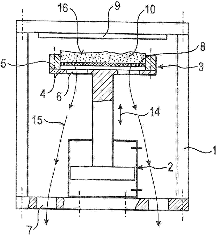
[0026] figure 1 A separation station according to a first embodiment is shown. Here, a lifting device 2 is arranged in the machine frame 1 , which is designed in the form of a solid adjusting piston with a piston rod suitable as a steel beam column. Lifting equipment is used to move the support bowl up and down 3. Up and down movement see direction arrow 14 for lifting movement. The support bowl consists of a flat plate 4 and has a circular cross section with an upwardly raised edge 5 surrounding the flat plate 4 . The plate 14 is provided with openings 6 through which the separated grinding oil can flow out, see directional arrow 15 for the direction of flow out. An opening 7 is provided for this purpose in the base plate of the frame 1 .

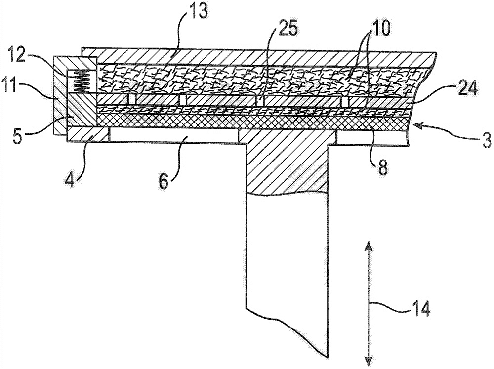
[0027] A permeable intermediate plate 8 is arranged at a distance above the plate 4 of the support bowl 3 . The intermediate plate can be designed as a sieve plate or as a plate with holes. The through-holes of the intermediate plat...


PUM


Abstract

The invention relates to a plant for separating grinding slurry originating from grinding machines into metal chips and grinding oil. According to the invention, a carrier bowl (3) in a frame (1) is filled with a divided volume of the grinding slurry (10). The carrier bowl (3) has a perforated plate (4) having an edge (5) as a floor and a sieve-like intermediate floor (8). By means of a lifting device (2), the carrier bowl (3) is moved to the effective region of an inductor plate (9) serving as a heater. The induction heat heats the ferromagnetic steel or iron particles present in the grinding slurry (10). Said heating effects a reduction in viscosity of the grinding oil in the grinding slurry (10), from which substantial portions flow downward through the openings (6) or (7). In certain cases, the effect can be improved by placing a steel plate on the free surface (16) of the grinding slurry layer (10).

Description

technical field [0001] The invention relates to a method for separating grinding oil from grinding sludge according to the preamble of claim 1 and a method for implementing the same according to the preamble of claims 16, 17 and 27. Method of separation station. Background technique [0002] Such a method and separation station are disclosed in DE19600505A1. [0003] Known methods aim to provide the prerequisites for the removal or reuse of individual grinding sludge components. By minimizing the grinding oil content of the grinding sludge, the metal components can be reused in the steelworks or foundry, or the grinding oil can be purified to such an extent that it can be recycled and reused. Known methods aim to reduce the outlay for the separation or cleaning process with low equipment and process outlay. For this purpose, according to the proposal of DE19600505A1, a method of mechanical separation by thermal process is proposed. Specifically, according to DE 19600505 ...

Claims


Application Information

Patent Timeline
Patent Type & Authority Applications(China)
IPC IPC(8): B24B57/00B28D5/00
CPCB01D29/843B01D29/824B24B57/00B01D29/09
Inventor 埃尓温·容克尓
Owner 埃尓温·容克尓机械制造有限公司
Why Eureka
Try Eureka