Grid-tie inverter

A technology of inverters and capacitors, applied in the field of system combined inverters, can solve problems such as leakage current and high-frequency noise that cannot be completely avoided

Active Publication Date: 2012-10-03
KK TOSHIBA
View PDF10 Cites 26 Cited by
  • Summary
  • Abstract
  • Description
  • Claims
  • Application Information

AI Technical Summary

Problems solved by technology

Therefore, there is a problem that leakage current and hi...

Method used


Image

  • Grid-tie inverter
  • Grid-tie inverter
  • Grid-tie inverter

Examples


Embodiment 1

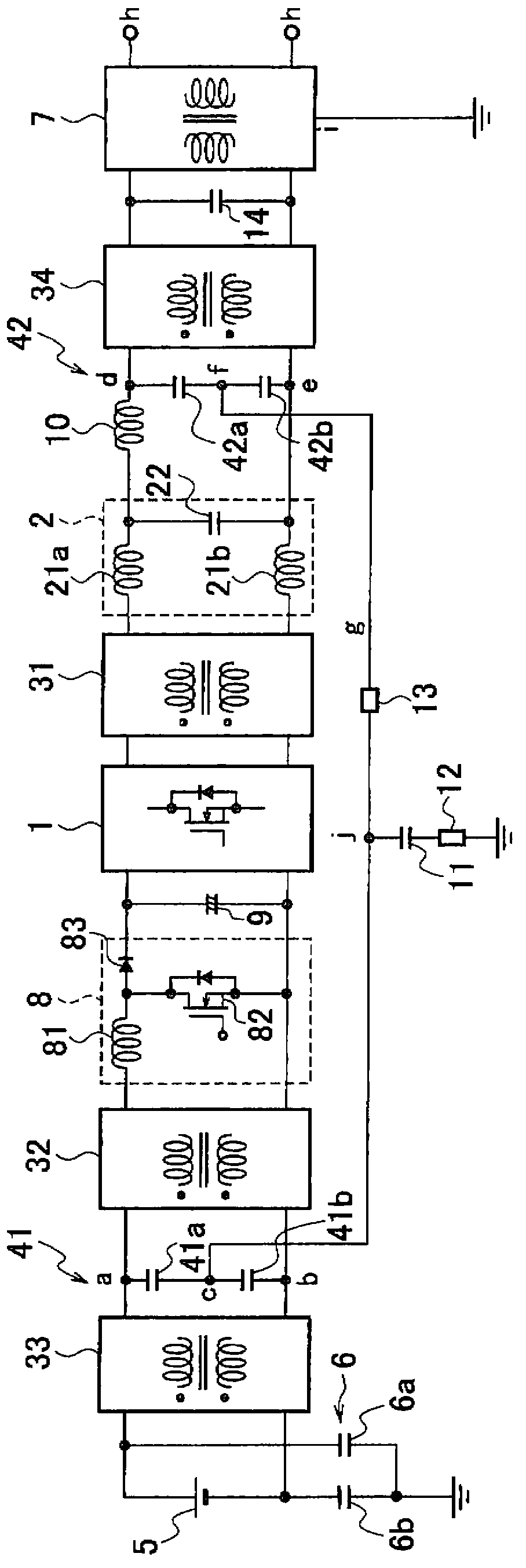
[0037] Such as figure 1 As shown, the grid-connected inverter of Embodiment 1 is a single-phase grid-connected inverter, and is configured as a solar power generation grid-connected inverter. In addition, in each of the following examples, with reference to figure 1 The structural elements of the system integrated inverter of the described embodiment 1 are the same as or equivalent to the structural elements, and are given the same as figure 1 Descriptions are made with the same symbols as those used in .

[0038] The combined system inverter of Embodiment 1 includes: an inverter 1, an output filter 2, a first common mode choke coil 31, a second common mode choke coil 32, a third common mode choke coil 33, a fourth common mode choke coil Common mode choke coil 34 , first capacitor pair 41 , second capacitor pair 42 , solar battery 5 , system transformer 7 , booster circuit 8 , DC linear capacitor (line condenser) 9 , normal mode (normal mode) reactor 10 , Grounded capacitor...

Embodiment 2

[0065] In the system joint inverter of embodiment 2, such as Figure 4 As shown, the first capacitor pair 41 of the system integrated inverter in Embodiment 1 is replaced with one first capacitor 41c, and the second capacitor pair 42 is replaced with one second capacitor 42c. From the connection point (point b) of the capacitor 41c and the output terminal on the negative side of the third common mode choke coil 33 (input terminal on the negative side of the second common mode choke coil 32) to the neutral point connection line g A capacitor 43a is inserted in the path up to point j above. A capacitor 43 b is inserted in the path from the connection point (point e) between the negative output terminal of the output filter 2 and the negative input terminal of the fourth common mode choke coil 34 to the second resistor 13 .

[0066]In the system combined inverter of Embodiment 1 above, the DC linear neutral point c formed on the input side of the inverter 1 and the AC output neu...

Embodiment 3

[0074] Such as Image 6 As shown, the grid-tie inverter of the third embodiment is configured such that the first reactor 21 ( 21 a , 21 b ) is removed from the output filter 2 of the grid-tie inverter of the first embodiment, and only the interphase capacitor 22 remains.

[0075] In the system combined inverter of Embodiment 1, the output filter 2 is composed of the first reactor 21 (21a, 21b) and the interphase capacitor 22, and the normal mode inductance component included in the first common mode choke coil 31 The same function as that of the first reactor 21 ( 21 a , 21 b ) of the output filter 2 is achieved. Therefore, in the grid-tie inverter of the third embodiment, the first reactor 21 ( 21 a , 21 b ) of the output filter 2 is replaced by the normal-mode inductance component of the first common-mode choke coil 31 .

[0076] According to the grid-tie inverter of Embodiment 3, like the grid-tie inverter of Embodiment 1 described above, leakage current and high-frequenc...


PUM


Abstract

The disclosed grid-tie inverter is provided with: a single-phase or three-phase inverter (1) which changes a DC voltage supplied from a DC power supply (5) to a pulse-width modulated voltage; a first capacitor circuit (41) which is connected so as to form a neutral point (c) on the input side of the inverter (1); a second capacitor circuit (42) which is connected so as to form a neutral point (f) on the output side of the inverter (1); a common mode current bypass channel (g) which is formed by connecting the neutral point (c) on the first capacitor circuit (41) and the neutral point (f) on the second capacitor circuit (42); a grounded capacitor (11) which is provided between the bypass channel (g) and the earth; a first common mode choke coil unit which is provided with common mode choke coils (31, 32) in at least one location between the first capacitor circuit (41) and the inverter (1) or the inverter (1) and the second capacitor circuit (42), and which uses the inverter (1) to suppress generated common mode current; and an output filter (2) which converts the pulse-width modulated voltage waveform output from the inverter (1) to a sinusoidal single-phase or three-phase AC voltage.

Description

technical field [0001] An embodiment relates to a grid-tie inverter (also called a grid-tie inverter), which converts a DC voltage supplied from a DC power source into an AC voltage, and integrates it with a power system of an electric company. Background technique [0002] In recent years, in grid-integrated inverters that convert DC voltage supplied from a DC power source such as a solar power generation system or a fuel cell into an AC voltage and integrate it with a power system, high-frequency switching has been developed. Subharmonic leakage current and electromagnetic noise (EMI: Electro-Magnetic Interference) become problems. Leakage current or EMI may affect the control of the inverter or other equipment or cause the leakage circuit breaker to malfunction. In Japan, the allowable amount of leakage current is regulated by the Electrical Appliance and Material Safety Law, and EMI is regulated by VCCI (Voluntary Control Council for Information Technology Equipment: In...

Claims


Application Information

Patent Timeline
IPC IPC(8): H02M7/48
CPCH02M7/48H02M2001/007H02M2001/123H02M1/126H02M1/123H02M1/007
Inventor 儿山裕史津田纯一饼川宏
Owner KK TOSHIBA
Why Eureka
Try Eureka