Flap assembly of aircraft
A technology of aircraft and flaps, which is applied in the field of aircraft flap assembly, can solve the problems of complex design, manufacture and installation, adverse effects on normal flight of aircraft, and high control accuracy requirements, so as to reduce manufacturing and maintenance costs and simplify the drive structure assembly. Integrating and improving the effect of control precision
- Summary
- Abstract
- Description
- Claims
- Application Information
AI Technical Summary
Problems solved by technology
Method used
Image

Examples
Embodiment Construction
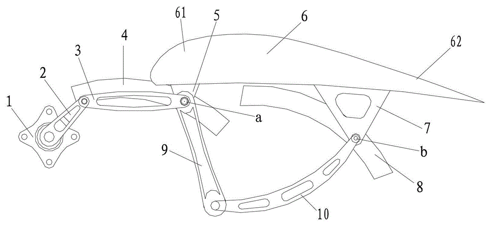
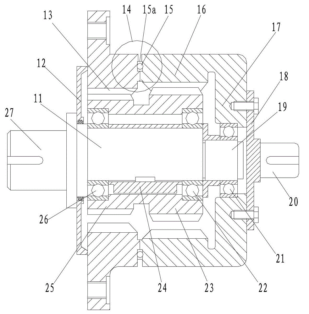
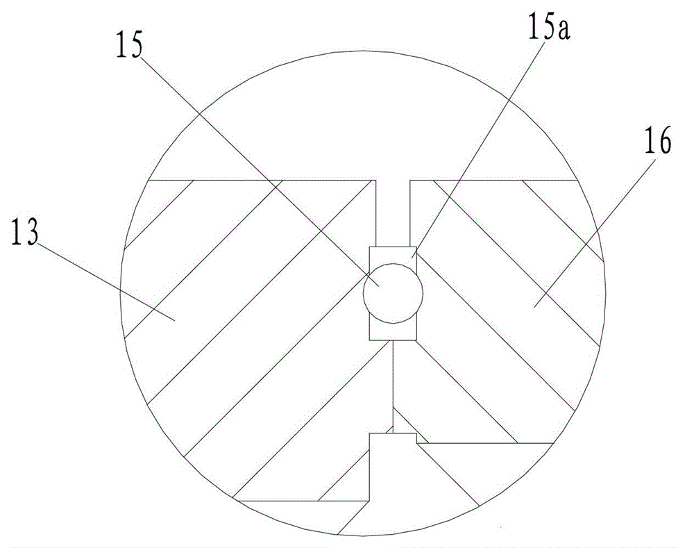
[0020] figure 1 It is a structural schematic diagram of the present invention, figure 2 It is a schematic diagram of the structure of the rotary drive output device, image 3 for figure 2 Enlarged view at place A, as shown in the figure: the aircraft flap assembly of the present invention includes a flap 6 and a drive assembly, and the drive assembly includes a rotary drive output device 1, a plane link mechanism and a pull rod 10, and the plane connection The rod mechanism is a swivel drive pair formed by sequentially hinged crank 2, connecting rod 3 and pressure rod 9. One end of the pull rod 10 is hinged forward to the rear end of the pressure rod 9, and the other end can move according to the set track at the hinge point. The way is hinged to the rear section 62 of the flap 6, the rotating power output end of the rotating drive output device 1 is connected to the head end of the crank 2, and the connecting rod 3 or / and the pressing rod 9 can move according to the set t...
PUM
 Abstract
Description
Claims
Application Information
 - Generate Ideas
- Intellectual Property
- Life Sciences
- Materials
- Tech Scout
- Unparalleled Data Quality
- Higher Quality Content
- 60% Fewer Hallucinations
Browse by: Latest US Patents, China's latest patents, Technical Efficacy Thesaurus, Application Domain, Technology Topic, Popular Technical Reports.
© 2025 PatSnap. All rights reserved.Legal|Privacy policy|Modern Slavery Act Transparency Statement|Sitemap|About US| Contact US: help@patsnap.com