Real-time monitoring method for large-size laser faculae

A laser spot, real-time monitoring technology, applied in the field of strong laser spot measurement, can solve the problems of increasing the experimental cost and system complexity, and achieve the effect of reducing the system complexity, reducing the experiment cost, and reducing the requirements of technical indicators

Inactive Publication Date: 2012-10-10
NAT UNIV OF DEFENSE TECH
View PDF6 Cites 6 Cited by
  • Summary
  • Abstract
  • Description
  • Claims
  • Application Information

AI Technical Summary

Problems solved by technology

The current method for monitoring the temporal and spatial distribution of laser-to-target power density encounters great difficulties in realizing the above two prerequisites
(1) It is difficult to establish a conjugate surface of the target surface on the optical path of the reference light
Because of the size limitation of the beam splitter, the beam splitter is generally placed before the beam expander system of the main optical path; unless another set of the same beam expander system is used, there will be no conjugate surface of the target surface on the reference beam optical path, which is undoubtedly Will increase experimental cost and system complexity
(2) It is difficult to find a power meter with a suitable caliber to receive all the beams at the target surface to calibrate the percentage of the laser power at the target surface to the total output power of the laser

Method used


Image

  • Real-time monitoring method for large-size laser faculae
  • Real-time monitoring method for large-size laser faculae

Examples


Embodiment Construction

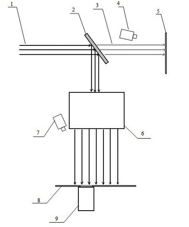
[0021] Calibration experiments are the key to the implementation of the present invention, and there are corresponding regulations in the current spot measurement methods for how to split light to form a reference beam, how to use a camera to capture a spot, and how to select a suitable attenuation film when shooting a spot. The specific implementation of the calibration experiment of the present invention will be further described below in conjunction with the accompanying drawings.

[0022] Such as figure 1 The schematic diagram of the calibration experiment principle is shown. The whole calibration system includes the beam splitter 2, the camera 4 used to measure the reference light spot, the diffuse screen 5 used to receive the reference light beam, the main optical system behind the beam splitter 6, and the main spot used for measuring the target surface. Camera 7, diffuse reflective screen 8 for receiving the light beam of the main optical path, and power meter 9 for tar...


PUM


Abstract

The invention relates to a real-time monitoring method for large-size laser faculae. The real-time monitoring method is characterized by comprising the following steps of: based on the linear transformation on a main light beam by using a beam expanding system behind a spectroscope, carrying out a calibration experiment, calculating a calibration linear transformation factor M, and characterizing the relative distribution of power density of target surface faculae by using reference light faculae through the calibration linear transformation factor M; and meanwhile, carrying out power sampling on local regions of the target surface faculae, and carrying out conversion to obtain laser-to-target power P0 by combining the percentage of grayscale values Di of corresponding regions of reference light faculae images accounting for the grayscale sum D0 of the images. According to the real-time monitoring method for the large-size laser faculae, another beam expanding system is not required for being introduced into a reference light path; and meanwhile, the requirements on related technical indicators of a laser power meter are reduced, the experiment cost is reduced, the complexity of an experimental system is reduced, and the density distribution of power from a large-size laser to a target can be monitored in real time, so that the real-time monitoring method is simple and feasible.

Description

technical field [0001] The invention relates to a method for measuring a strong laser spot, in particular to a real-time monitoring method for the temporal and spatial distribution of a large-scale laser spot. Background technique [0002] Laser spot measurement, especially to obtain the spatiotemporal distribution characteristics of the laser-to-target power density, is very important in the study of the irradiation effect of intense laser on the target, and it may determine the main physical mechanism of the interaction between the laser and the target. The commonly used method is to separate a weak beam of reference light through the beam splitter in the main optical path, record the reference light spot in real time by the camera, and calibrate the percentage of the laser power at the target surface to the total output power of the laser to obtain the laser to Absolute spatiotemporal distribution of target power density. The application of this monitoring method obvious...

Claims


Application Information

Patent Timeline
Patent Type & Authority Applications(China)
IPC IPC(8): G01J1/10G01J1/00
Inventor 江厚满杨轶赵国民张烜喆刘磊齐恩宇康磊
Owner NAT UNIV OF DEFENSE TECH
Why Eureka
Try Eureka