PLZT electro-optic controllable phase delayer

A phase retarder, electro-optical technology, applied in instruments, optics, nonlinear optics, etc., can solve the problems of not finding a large clear aperture, and the electrode spacing cannot be made too large, and achieve a large controllable range of phase delay and low switching. The effect of voltage and large field of view

Inactive Publication Date: 2012-10-10
TSINGHUA UNIV
View PDF5 Cites 5 Cited by
  • Summary
  • Abstract
  • Description
  • Claims
  • Application Information

AI Technical Summary

Problems solved by technology

However, this material has hysteresis effect, because it is an electric field device, so considering the voltage, the electrode spacing cannot be made too large, so there is no PLZT electro-optic switch with a large optical aperture, let alone a fast response large optical aperture. PLZT electro-optic controllable phase retarder, because the electro-optical switch can be composed of a controllable phase retarder whose phase delay varies between two fixed values ​​and a responsive polarizer and a fixed phase retarder, therefore, it achieves fast response Responsive PLZT electro-optic controllable phase retarder with large optical aperture can also produce corresponding high-speed PLZT electro-optic switch with large optical aperture

Method used


Image

  • PLZT electro-optic controllable phase delayer
  • PLZT electro-optic controllable phase delayer
  • PLZT electro-optic controllable phase delayer

Examples


Embodiment Construction

[0028] The specific implementation manners of the present invention will be further described in detail below in conjunction with the accompanying drawings and embodiments. The following examples are used to illustrate the present invention, but are not intended to limit the scope of the present invention.

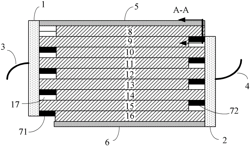
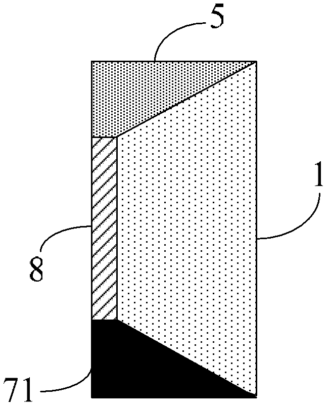
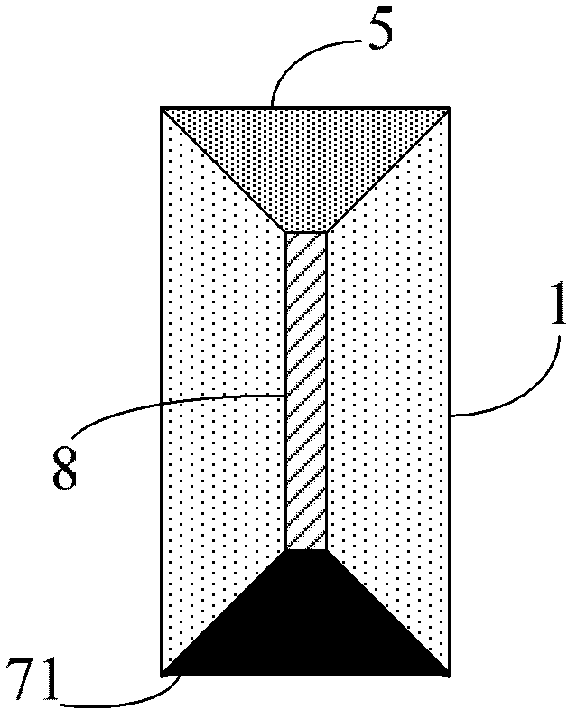
[0029] The front structure of the PLZT electro-optic controllable phase retarder proposed by the present invention is as follows figure 1 As shown, two wires 3 and 4 are respectively connected to the two side electrodes 1 and 2, and are connected to the two poles of the power supply to realize applying voltage to the electro-optic switch. The end electrode 5 (the first end electrode) and the end electrode 6 (the first End electrodes) are respectively located at the upper and lower ends of the arrayed strip-shaped PLZT unit array, the end electrodes 5 are connected to the side electrodes 1 (first side electrodes), and the end electrodes 6 are connected to the side electrode...


PUM


Abstract

The invention discloses a PLZT electro-optic controllable phase delayer, relating to the field of photoelectric technology. The phase delayer is characterized in that: the PLZT electro-optic controllable phase delayer includes a PLZT array formed by several strip-shaped PLZTs, and two groups of electrodes formed around the PLZT array, a first surface of a PLZT located in the middle contacting a second surface of a PLZT adjacent to the PLZT located in the middle, the second surface contacting a first surface of another PLZT adjacent to the PLZT located in the middle, both of the two contacting surfaces being plated with conductive material; the first group of the electrodes are used for applying a first voltage to first surfaces of the Nth (N is odd number) PLZTs and applying the first voltage to second surfaces of the Nth (N is even number) PLZTs; and the second group of the electrodes are used for applying a second voltage to second surfaces of the Nth (N is odd number) PLZTs and applying the second voltage to first surfaces of the Nth (N is even number) PLZTs. The PLZT electro-optic controllable phase delayer provided in the invention is advantaged in low working voltage, large controllable range of phase delay amount and rapid response.

Description

technical field [0001] The invention relates to the field of optoelectronic technology, in particular to a PLZT electro-optic controllable phase retarder. Background technique [0002] Under the action of an external electric field, the birefringence properties of some substances will change, which is the electro-optic effect. Using this electro-optic effect, it can be made into electro-optic switches, electro-optic modulators, beam deflectors and other devices. Common electro-optic effects include the first-order electro-optic effect and the second-order electro-optic effect. The first-order electro-optic effect is called the Pockels effect, and the second-order electro-optic effect is called the Kerr effect. [0003] The Pockels effect refers to the fact that when an electric field is applied, the birefringence induced in the object is only proportional to the first power of the electric field. There are many crystals with this type of electro-optic effect, such as: ADP ...

Claims


Application Information

Patent Timeline
Patent Type & Authority Applications(China)
IPC IPC(8): G02F1/03
Inventor 巩马理王涛柳强闫平黄磊张海涛刘欢
Owner TSINGHUA UNIV
Why Eureka
Try Eureka