Method for splicing maskless digital projection lithography pattern

A maskless, projection light technology, applied in the field of maskless lithography, can solve the problems of line dislocation, wrapping, overlapping, etc., to achieve low cost, improve quality, and solve the effect of distortion

Inactive Publication Date: 2012-10-10
INST OF OPTICS & ELECTRONICS - CHINESE ACAD OF SCI
View PDF5 Cites 16 Cited by
  • Summary
  • Abstract
  • Description
  • Claims
  • Application Information

AI Technical Summary

Problems solved by technology

[0003] However, due to the limited single etching area of ​​this lithography technology, and factors such as environmental vibration interference and the displacement accuracy of the workpiece table have a huge impact on the precise position of the f

Method used


Image

  • Method for splicing maskless digital projection lithography pattern
  • Method for splicing maskless digital projection lithography pattern
  • Method for splicing maskless digital projection lithography pattern

Examples


Example Embodiment

[0033] In order to make the objectives, technical solutions, and advantages of the present invention clearer, the following further describes the present invention in detail in conjunction with specific embodiments and with reference to the accompanying drawings.
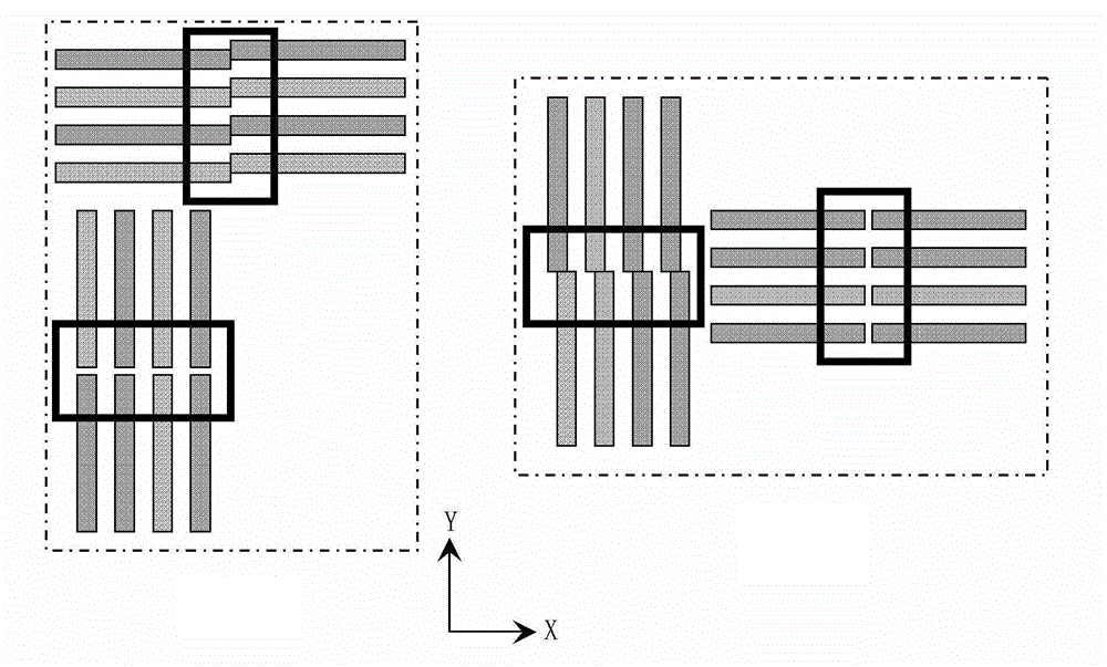
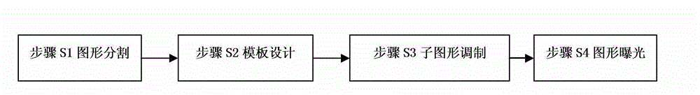
[0034] Such as figure 1 As shown in the figure, the present invention provides a pattern splicing method suitable for digital micro-mirror maskless digital lithography. The pattern to be etched is divided, the template is designed, the sub-pattern is modulated by the corresponding template, and the modulated sub-pattern is exposed frame by frame. Among them, before the actual writing operation, the pattern to be etched is divided into multiple frames of sub-graphics with a size of 1024×768 pixels, and then each sub-graphic is multiplied by the designed corresponding template to realize the pre-processing of the sub-graphics. Digital micromirror maskless digital projection lithography for large-area graphics exposure, du...


PUM


Abstract

The invention relates to a method for splicing maskless digital projection lithography pattern. The method comprises the steps of S1 segmenting a pattern to be etched to obtain multiple segmented frames of sub-pattern, wherein each frame of sub-pattern is of same size; S2 setting a template size which is the same with the size of each frame of sub-pattern; S3 multiplying each segmented frame of sub-pattern by the template to obtain a boundary splicing region of the sub-pattern, and employing a gray modulation template to modulate the gray value of the boundary splicing region to obtain the modulated sub-pattern; S4 carrying out exposure on the modulated sub-pattern frame-by-frame with digital micromirror display to realize the splicing of the reproduction transfer of the modulated sub-pattern which is displayed by the digital micromirror to a substrate. The method provided by the invention can fairly solve the splicing problem which exists when a pattern with a large area is etched, thus the etching quality of the digital projection lithography pattern is improved.

Description

technical field [0001] The invention belongs to the technical field of maskless lithography, and in particular relates to a pattern splicing method suitable for maskless digital projection lithography. Background technique [0002] With the rapid development of micro-optical, mechanical, electrical and other technologies, micro-fabrication technology has developed rapidly. Micro-optical components are widely used in the fields of communication, military, space technology, super-finishing, biomedicine, and information processing. This has led researchers to conduct extensive research on the design, fabrication and application of micro-optics. Micro-optics has made great progress in design theory and manufacturing methods. In order to further expand the application field of micro-optics components, higher requirements are put forward for its manufacturing methods. Therefore, it is still an extremely important research direction in the field of micro-optics at home and abroad...

Claims


Application Information

Patent Timeline
IPC IPC(8): G03F7/20G06T7/00
Inventor 朱江平胡松陈铭勇唐燕何渝
Owner INST OF OPTICS & ELECTRONICS - CHINESE ACAD OF SCI
Why Eureka
Try Eureka