Self-turnoff component driving protection circuit

A drive protection circuit, self-shutdown technology, applied in the field of power electronics, can solve the problems of long shutdown time, low overcurrent capability, low sensitivity, etc., to suppress overvoltage and oscillation, achieve desaturation protection, and ideal waveform stability Effect

Inactive Publication Date: 2012-10-10
柏德胜 +2
View PDF5 Cites 15 Cited by
  • Summary
  • Abstract
  • Description
  • Claims
  • Application Information

AI Technical Summary

Problems solved by technology

In the former circuit, the clamping diode and the potential compensation diode can make the high-power transistor always in a critical saturation state when it is turned on, and the Zener diode and the reverse bias diode can accelerate the turn-off of the high-power transistor when it is cut off, but the stability of the Zener transistor It is difficult to determine the voltage value, too low reverse bias effect is not obvious, too high will damage the power components, and may produce high-frequency parasitic oscillation
Self-shutdown devices such as high-power transistors generally have relatively small heat capacity and low overcurrent capability. When they operate in an inverter system, due to their long shutdown time, they are likely to cause short-circuit faults in the bridge arm, and the latter circuit adopts state Identification protection is less sensitive to monitoring under light overload conditions
The above discrete component drive protection circuits all have the disadvantages of many components, complex circuits, poor stability and inconvenient use.

Method used


Image

  • Self-turnoff component driving protection circuit
  • Self-turnoff component driving protection circuit
  • Self-turnoff component driving protection circuit

Examples


Embodiment Construction

[0017] The specific embodiments of the present invention will be further described in detail below in conjunction with the accompanying drawings.

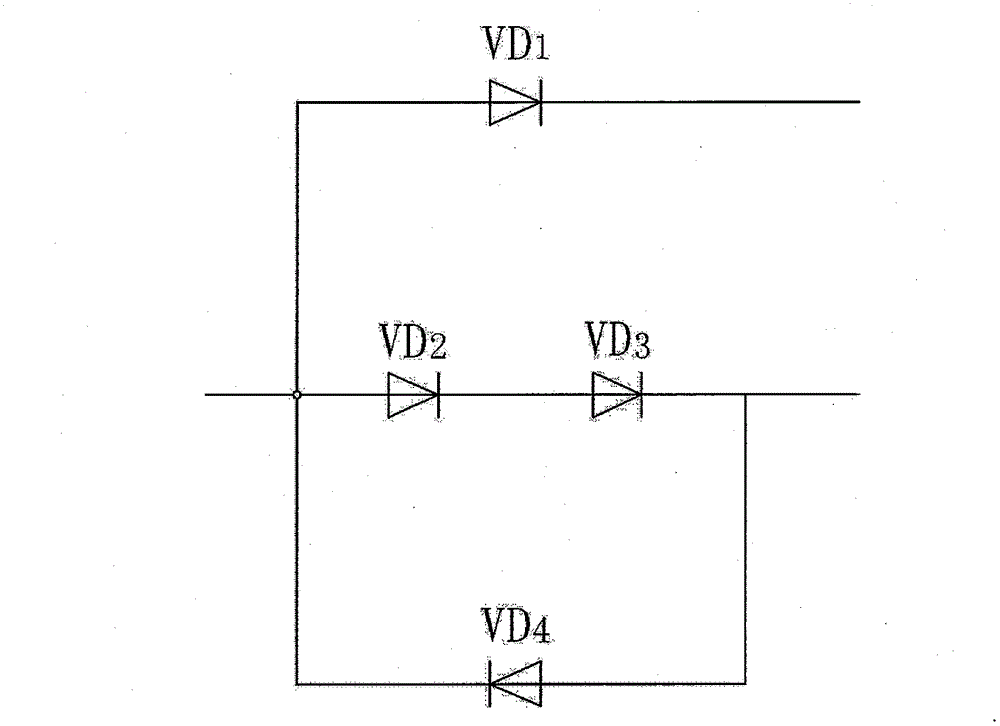
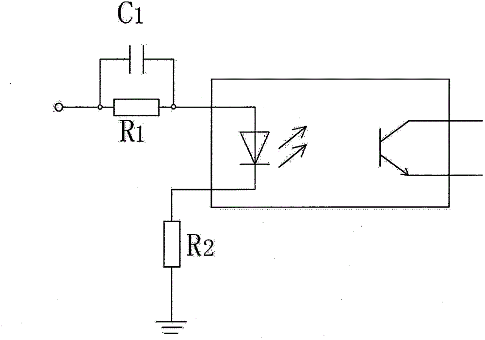
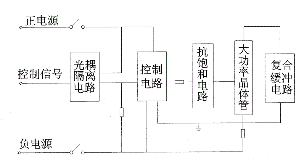
[0018] Such as figure 1 , figure 2 As shown, the present invention includes a positive and negative power supply, an optocoupler isolation circuit, a control circuit, an anti-saturation circuit, a high-power transistor, and a composite buffer circuit.

[0019] The control signal of the circuit is filtered by R1 and C1 and then input to the anode of the primary light-emitting diode of the optocoupler O1, the negative pole of the light-emitting diode is grounded through the resistor R2, and the emitter of the secondary phototransistor of the optocoupler O1 is directly connected to the chip in the control circuit The input terminal of UAA4002 is connected to the negative power supply -Vcc through resistor R3 and switch S2, and the positive power supply Vcc is connected to the collector of the phototransistor through switch S1. The ...


PUM


Abstract

The invention relates to a self-turnoff component driving protection circuit which particularly comprises positive and negative power supplies, an optical coupler isolating circuit, a control circuit, an anti-saturation circuit, a high power transistor and a composite buffer circuit, wherein a control signal current is subjected to resistance-capacitance filtering and is subsequently input into the anode of a primary light emitting diode of the optical coupler component; an emitter electrode of a secondary phototriode of the optical coupler component is directly connected with the input end of a chip UAA4002 in the control circuit; the positive power supply is connected with the collector electrode of the phototriode through a switch; the positive and negative power supplies are respectively connected with positive and negative power supply pins of the chip UAA4002 and are respectively connected with the collector electrodes of subsequent upper and lower pair tubes, the control circuit is connected with the anti-saturation circuit through a current-limiting resistor; the anti-saturation circuit is connected in parallel between the base electrode and the collector electrode of the high power transistor; and the composite buffer circuit is directly connected in parallel between the collector electrode and the emitter electrode of the high power transistor; thereby a self-turnoff component driving protection circuit which is simple in circuit structure, complete in function, high in reliability, small in switch consumption and rapid in protection response is provided.

Description

technical field [0001] The invention belongs to the technical field of power electronics, and in particular relates to a driving protection circuit for a self-shutoff device. Background technique [0002] The function of the drive protection circuit for self-turn-off devices such as high-power transistors is to amplify the control signal current output by the control circuit enough to ensure that the self-turn-off devices can be turned on and off reliably. The base drive mode of the high-power transistor directly affects its working condition, which can improve or damage certain characteristic parameters. The drive protection circuit should match the main circuit to ensure that the high-power transistor is in a quasi-saturation state at any time during the conduction period. When it is turned off, a sufficient reverse bias voltage can be quickly applied, and it has sufficient protection functions. At present, high-power transistors mostly use a base drive circuit topology w...

Claims


Application Information

Patent Timeline
Patent Type & Authority Applications(China)
IPC IPC(8): H03K17/78H03K17/08
Inventor 柏德胜杨佐峰王明才
Owner 柏德胜
Why Eureka
Try Eureka