Flow control device for alloy liquid

A flow control device and alloy liquid technology, which is applied in the control of pouring molten metal from the ladle, manufacturing tools, metal processing equipment, etc. Yield is not easy to guarantee and other problems, to achieve the effect of improving labor productivity, simple structure and convenient operation

Active Publication Date: 2014-06-18
ANHUI CHUJIANG TECHCAL NEW MATERIAL CO LTD
View PDF3 Cites 1 Cited by
  • Summary
  • Abstract
  • Description
  • Claims
  • Application Information

AI Technical Summary

Problems solved by technology

However, with this structure of the control device, when the stopper rod and screw are rotating, the degree of opening and closing of the joint surface between the two is difficult to grasp, making it difficult to control the flow rate of the alloy liquid, which leads to the ingot crystallization process. The efficiency is not easy to guarantee, which not only increases the labor intensity of the operator, but also puts forward higher requirements for the operation skills of the operator, thus affecting the labor productivity.

Method used


Image

  • Flow control device for alloy liquid
  • Flow control device for alloy liquid
  • Flow control device for alloy liquid

Examples


Embodiment Construction

[0020] Below with reference to the accompanying drawings, through the description of the embodiments, the specific embodiments of the present invention, such as the shape, structure, mutual position and connection relationship between the various parts, the role and working principle of the various parts, etc., will be further described. Detailed instructions:

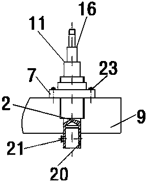
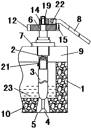
[0021] as attached figure 1 — attached Figure 4 As shown, the present invention is an alloy liquid flow control device. The flow control device includes an alloy liquid chamber 1, a screw 2 threadedly connected with the alloy liquid chamber 1, and the screw rod 2 is located at the end of the alloy liquid chamber 1. A graphite stopper rod 3 is installed at the head position, and a graphite base 5 with a through hole 4 is arranged on the alloy liquid chamber 1. When the screw rod 2 is screwed into one end located inside the alloy liquid chamber 1, the graphite stopper rod 3 is set to continuously approach The structur...


PUM


Abstract

The invention provides a flow control device for alloy liquid, which is applied to the technical field of alloy processing. The flow control device comprises an alloy liquid accommodating cavity (1) and a screw (2), wherein the screw (2) is in threaded connection with the alloy liquid accommodating cavity (1), an end position (located in the alloy liquid accommodating cavity (1)) of the screw (2) is provided with a graphite stopper (3), a graphite base (5) with a through hole (4) is arranged on the alloy liquid accommodating cavity (1), when the screw (2) is screwed in one end of the inside of the alloy liquid accommodating cavity (1), the graphite stopper (3) is set into a structure of constantly being close to the through hole (4) in the graphite base (5), and after the graphite stopper (3) is constantly screwed in, the graphite stopper (3) is set into a structure which can jam the through hole (4). The flow control device for alloy liquid, provided by the invention, is simple in structure, can easily control the flow of the alloy liquid flowing out of the alloy liquid accommodating cavity (1), and can conveniently realize the connection and disconnection of the flow at any time; and meanwhile, due to the structure of the flow control device provided by the invention, the flow control device is convenient to operate and reduces the operation difficulty of the operating personnel.

Description

technical field [0001] The invention belongs to the technical field of alloy processing, and more specifically relates to an alloy liquid flow control device. Background technique [0002] When using the traditional semi-continuous casting process to produce alloy ingots, it is necessary to control the flow rate of the alloy liquid. At the beginning of casting, the existing control device and method are: the alloy liquid is released by a round rod with a square tenon The stopper rod screw in the hole rotates, so that the alloy liquid flows out from the joint surface of the graphite stopper rod and the graphite base. However, with this structure of the control device, when the stopper rod and screw are rotating, the degree of opening and closing of the joint surface between the two is difficult to grasp, making it difficult to control the flow rate of the alloy liquid, which leads to the ingot crystallization process. The efficiency is not easy to guarantee, which not only i...

Claims


Application Information

Patent Timeline
Patent Type & Authority Patents(China)
IPC IPC(8): B22D41/16B22D37/00B22D39/00
Inventor 莫云龙胡兵何晟卢卫安陈鑫
Owner ANHUI CHUJIANG TECHCAL NEW MATERIAL CO LTD
Why Eureka
Try Eureka