Hydraulic pressure machine

A press and hydraulic technology, applied in the field of non-cutting metal forming processing equipment, can solve the problems of low work efficiency, poor working environment, difficult large-tonnage stamping operations, etc.

Inactive Publication Date: 2012-10-17
SHANDONG UNIV OF SCI & TECH
View PDF0 Cites 0 Cited by
  • Summary
  • Abstract
  • Description
  • Claims
  • Application Information

AI Technical Summary

Problems solved by technology

[0003] The purpose of the present invention is to solve the above-mentioned shortcomings of existing mechanical presses such as difficulty in realizing large-tonnage stamping operations, and traditional hydraulic presses such as low work efficiency and poor working environment. The present invention provides a hydraulic press, which The press is a typical multi-link hydraulic press. It is driven by a hydraulic cylinder with two sets of booster mechanisms, which can make the hammer have high efficiency and large tonnage.

Method used


Image

  • Hydraulic pressure machine

Examples


Embodiment Construction

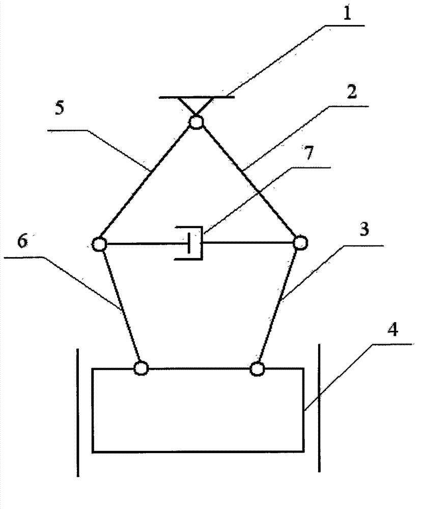
[0007] Such as figure 1 The specific embodiment of the present invention shown is a hydraulic press, and the press includes a frame 1, an upper link 2 of the right branch, a lower link 3 of the right branch, a hammer 4, The upper link 5 of the left branch chain, the lower link 6 of the left branch chain and the hydraulic cylinder 7, the frame 1 and the hammer 4 are connected by two identical left and right branch chains; the right branch chain is composed of the upper link 2 and the hydraulic cylinder 7. The lower connecting rod 3 is connected through a rotating pair; the left branch chain is connected with the upper connecting rod 5 and the lower connecting rod 6 through a rotating pair; The hammer 4 is connected; the upper link 5 and the lower link 6 of the left branch chain are respectively connected with the frame 1 and the hammer 4 through the rotary pair; one end of the hydraulic cylinder 7 is connected with the upper link 2 of the right branch chain through the rotary p...


PUM


Abstract

The invention relates to a hydraulic pressure machine, comprising a rack, an upper connecting rod of a right branch chain, a lower connecting rod of the right branch chain, a punching hammer, an upper connecting rod of a left branch chain, a lower connecting rod of the left branch chain and a hydraulic cylinder, wherein the rack is connected with the punching hammer by the left branch chain and the right branch chain which are same; the right branch chain is formed by the upper connecting rod and the lower connecting rod which are connected by a rotating pair; the left branch chain is formed by the upper connecting rod and the lower connecting rod which are connected by a rotating pair; the upper connecting rod and the lower connecting rod of the right branch chain are respectively connected with the rack and the punching hammer by a rotating pair; the upper connecting rod and the lower connecting rod of the leftt branch chain are respectively connected with the rack and the punching hammer by a rotating pair; one end of the hydraulic cylinder is connected with the upper connecting rod and the lower connecting rod of the right branch chain by a rotating pair at the same point, and the other end of the hydraulic cylinder is connected with the upper connecting rod and the lower connecting rod of the left branch chain by a rotating pair at the same point; and the punching hammer is fixed in a guide rail and is connected with the rack by a movable pair. The hydraulic pressure machine has the advantages that two sets of force increasing mechanisms are driven by utilizing the hydraulic cylinder, so that high-efficiency, large-tonnage and high-stability stamping operation can be obtained, and simultaneously the difficulty for controlling the synchronous and coordinated movement of the two branch chains can be avoided.

Description

technical field [0001] The present invention relates to non-cutting metal forming processing equipment, in particular to a hydraulic press. Background technique [0002] Presses are one of the most important metal forming processing equipment and are widely used in industrial production. At present, there are two main types of presses: mechanical presses and hydraulic presses. The working mechanism of the mechanical press is a centering crank slider mechanism or other types of multi-link mechanism. It has the characteristics of high processing efficiency, good working environment and convenient maintenance, but it is not suitable for large-tonnage stamping operations. Traditional hydraulic presses can achieve large-tonnage stamping operations, but the work efficiency is low and the working environment is poor. Therefore, fully combining the advantages of mechanical presses and hydraulic presses to develop a new type of multi-link hydraulic press is an urgent problem to be ...

Claims


Application Information

Patent Timeline
Patent Type & Authority Applications(China)
IPC IPC(8): B30B1/32
Inventor 陈修龙邓昱
Owner SHANDONG UNIV OF SCI & TECH
Why Eureka
Try Eureka