
Rack and pinion steering

A technology of steering device and pinion, which is applied in the direction of steering gear, steering mechanism, mechanical steering gear, etc., can solve the problem of troublesome operation noise risk, and achieve the effect of simplifying the whole structure

Inactive Publication Date: 2016-12-14
FORD GLOBAL TECH LLC
View PDF6 Cites 0 Cited by
  • Summary
  • Abstract
  • Description
  • Claims
  • Application Information

AI Technical Summary

Problems solved by technology

Furthermore, the steering mechanism in DE 36 13 030 A1 has a troublesome risk of operating noise at relatively large steering angles, since in this case the rack is only guided by the rollers and not by the yoke

Method used


Image

  • Rack and pinion steering

Examples


Embodiment Construction

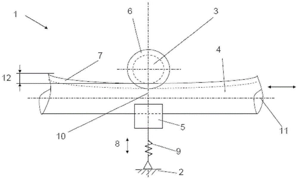
[0041] figure 1 A partial plan view of an embodiment of the rack and pinion steering device 1 according to the present invention is shown. The rack and pinion steering device 1 includes a drive pinion 3 rotatably installed in the steering device housing 2, a rack 4 that can be moved axially in the steering device housing 2, and axially movable in the steering device housing 2. 的压件5。 Pressure piece 5. The rotatable installation of the drive pinion 3 and the axially movable installation of the rack 4 and the pressure member 5 are done in the traditional way, so they are not figure 1 Specific display. The steering gear housing 2 is similarly only in figure 1 Schematic instructions.

[0042] In the embodiment shown, figure 1 The steering device 1 shown in is a part of a steering device (not shown in the figure) of a vehicle, especially a motor vehicle. For this purpose, the drive pinion 3 is connected to the steering device end of the steering column for common rotation therewit...


PUM


Abstract

The rack and pinion steering gear (1) comprises a drive pinion (3), which is rotatably mounted in a steering housing (2) engaged with an toothing section of a rack (4). The rack is axially displaced into the steering housing. A pressure piece (5) is provided, which is axially movable in the steering housing against the rack in a spring loaded manner for preloading the rack opposite to the drive pinion. The diameter of the rack increases in the toothing section, starting from central area (10) towards the axial ends of the rack.

Description

Technical field [0001] The invention relates to a rack and pinion steering device. Background technique [0002] Many specific embodiments of rack and pinion steering devices are known. They usually have a steering gear housing that allows the rack to move axially, that is, longitudinally. The drive pinion rotatably installed in the steering device housing meshes with the teeth on the rack, and when the steering column of the vehicle, especially the steering device of a motor vehicle, rotates, it is connected to the drive pinion for co-rotating with the said The steering column causes a lateral displacement of the rack, which in turn causes the steering wheels of the motor vehicle to pivot by means of tie rods and steering knuckles. The meshing of the drive pinion in the rack is kept free of play by pressing the rack against the drive pinion under a spring load by means of a pressure member, which abuts on the rack on the opposite side of the drive pinion. Regarding this point...

Claims


Application Information

Patent Timeline
Patent Type & Authority Patents(China)
IPC IPC(8): B62D3/12
CPCB62D3/126B62D3/123
Inventor 托斯滕·克卢格迈克尔·乔治·菲古拉
Owner FORD GLOBAL TECH LLC
Learn More